8 min read
How to Test a John Deere Voltage Regulator (7 Steps)

A John Deere voltage regulator controls the electrical current from your John Deere lawn tractor’s stator so that its battery can be charged with a smooth current without damaging it.
It is critical to regularly test a John Deere voltage regulator to verify that it’s in good functioning order and that, if a problem arises, you can address it quickly to prevent damaging your vehicle.
In general, to test a John Deere voltage regulator, use a multimeter and:
- Locate the voltage regulator and set the multimeter to measure ohms for a continuity test.
- Connect the multimeter’s black lead to the ground.
- Connect the multimeter’s red lead to each of the three prongs.
- The reading should be within the range specified by the manufacturer (low resistance, such as 0.04-0.05 ohms).
In this article, I will show how the voltage regulator works and give you more details on testing your John Deere voltage regulator.
Testing a John Deere Voltage Regulator (Continuity Test)
You will need a multimeter (or an ohmmeter and a voltmeter) to test a John Deere voltage regulator.
Before that, we will use a test light to check whether the voltage regulator is getting power and how good the grounding is.
Follow the steps given below.
Step 1: Locate the Voltage Regulator
Park your John Deere on a hard and level surface and locate its voltage regulator.
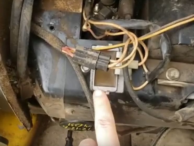
Set its parking brake and remove the key from the ignition. Raise the hood and look for the voltage regulator, which is usually on the right side of the engine. You can locate the regulator in the little silver box attached to the engine’s side.
If it’s a John Deere lawnmower, still look for a small silver box attached on one side, as shown below.
Step 2: Use the Test Light
This is optional to check whether the voltage regulator is getting power.
First, turn the ignition on.
Then, hook the negative lead of the test light to the battery’s negative terminal and attach the positive probe to the voltage regulator’s power supply terminal. The light should come on.
Attach the test light’s negative side to the battery’s positive terminal and the positive probe to the ground point near the voltage regulator. The light should come on again.
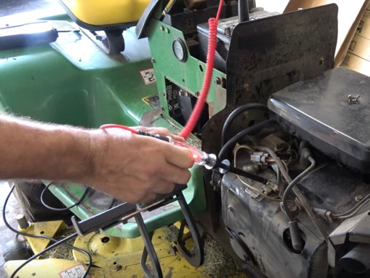
Having power at the voltage regulator confirms that you have a direct route from the battery to the voltage regulator, and the ground test confirms you have a decent ground.
If the test light hadn’t come on, the voltage regulator might not be at fault. You should check the wiring to it instead. You should also test the stator (for the correct AC voltage) to rule out the stator. Otherwise, proceed to check the voltage regulator.
Step 3: Set the Multimeter
Turn on your multimeter and set it to the ohms scale, which will measure resistance to indicate continuity.
We will conduct a continuity test.
Step 4: Connect the Ground Lead
Disconnect the voltage regulator’s plug from the bottom.
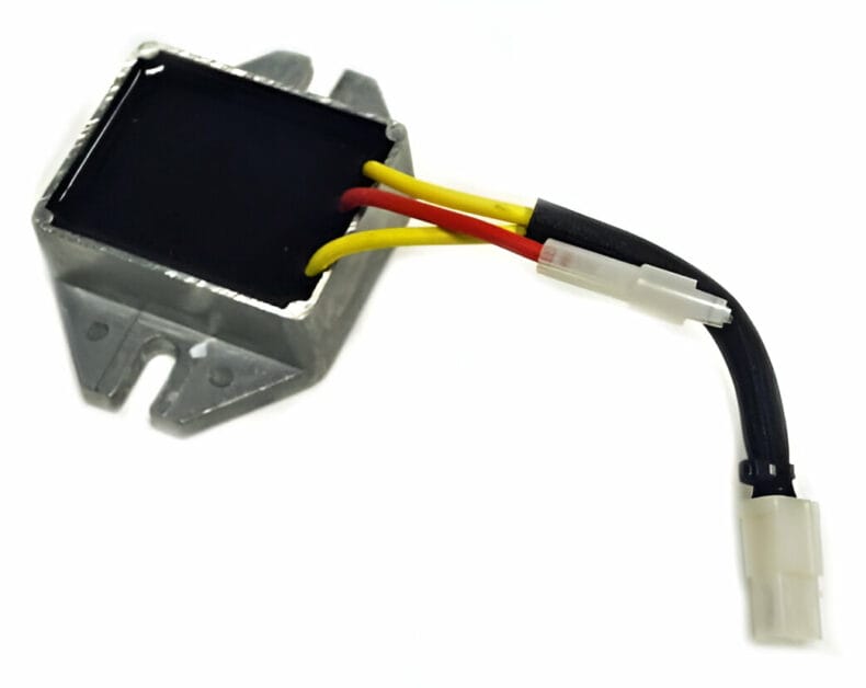
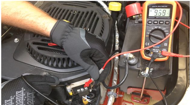
Look for the ground wire under the bolt that secures the voltage regulator to the engine block. Connect the multimeter’s black (ground) lead to the bolt with the ground wire underneath it. You will see three prongs under the voltage regulator.
Step 5: Connect the Positive Lead
Connect the multimeter’s red probe or lead to the prong furthest from the ground. Usually, it’s the one at the opposite end.
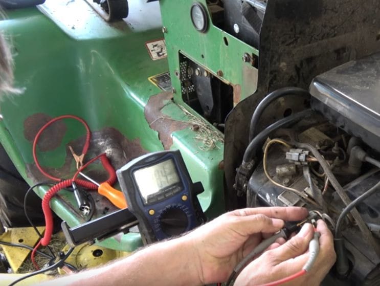
The reading should be within the range specified by the manufacturer.
Check the vehicle owner’s manual or the manufacturer’s website. In the above example, the reading of 0.04 ohms shows a low resistance (so, a good path for current to flow).
You should replace the voltage regulator if it’s outside the specified range. If it’s very high, infinite, or remains on OL on the display, there is no continuity, so it must be replaced. The same applies in the subsequent steps for the other 2 prongs.
Continue to the next step if the reading is correct.
Step 6: Test the Middle Prong
Transfer the red probe to the middle prong while keeping the black probe in place.
The multimeter’s reading should again be within the specified range. If it’s not, the voltage regulator must be replaced. Continue to the next step if the reading is correct.
Step 7: Test the Closest Prong
Keeping the black lead on the ground, move the red lead to the prong closest to the ground.
Check the reading. The multimeter’s reading should be within the specified range. If that’s not the case, the voltage regulator must be replaced. But your voltage regulator is in good condition if all of these readings are correct and within the range.
Testing a John Deere Voltage Regulator via the Battery (Voltage Test)
You can also perform a John Deere voltage regulator test through its battery by testing its voltage. Here are the steps:
Step 1: Set Up the Vehicle
Make sure you park your vehicle on a flat, hard surface. Turn the ignition key to the “off” position and set its parking brake.
Step 2: Load the Battery
Return to the “neutral” position with the foot pedal.
Then, raise the tractor’s hood and turn the ignition key one position over to turn on the mower’s headlights without turning the engine over for 15 seconds to put a slight load on the battery.
Step 3: Connect the Leads to the Battery
Turn your multimeter or voltmeter on.
Set it to the 20 or 50-volt DC scale. Connect its positive (red) lead to the battery’s positive (+) terminal and the negative lead to the battery’s negative (-) terminal.
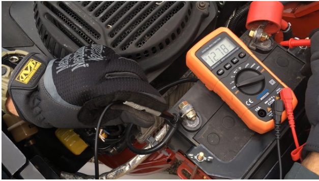
Step 4: Check the Reading
Start your vehicle’s engine and set the throttle to its fastest position.
Over five minutes of operation, the battery voltage should remain between a 12.2- and 14.7-volt DC reading.
FAQs
What exactly is John Deere’s voltage regulator?
The voltage regulator of a John Deere lawnmower ensures that the machine’s battery receives a steady, continuous charge.
It runs on a 12-volt system to keep its battery charged. The stator on top of the engine must generate 14 volts to send back to the battery. The 14 volts must pass via the voltage regulator, which evens out the voltage-current, ensuring that the battery and electrical system are not damaged.
The AM102596, for example, is a voltage regulator used on single-cylinder Kohler engines in John Deere lawn tractors. The voltage regulator regulates the electrical current flowing from the stator, ensuring that the battery is charged at a steady rate that will not damage it.

References
Website Resources:
- electrical system. https://www.britannica.com/technology/electrical-system
- lawn. https://extension.umn.edu/lawncare/environmental-benefits-healthy-lawns
- John Deere Voltage Regulator. https://www.greenpartstore.com/John-Deere-Voltage-Regulator-MIU14388.html#mz-expanded-view-242179778325
Video References:
Farm Ground, Country Strong
Wtbm123