10 min read
Kawasaki Voltage Regulator Test (3 Methods)

Conducting a voltage regulator test on a Kawasaki or any other vehicle can be complicated. That’s why I have put together this easy-to-follow guide with illustrations.
Here is a quick summary of the three methods I will go through:
Testing the Voltage Across the Battery’s Terminals:
- Turn off the engine.
- Connect a voltmeter across the battery’s terminals.
- Note the voltage – it should be a little over 12 volts.
- Start the engine and observe the voltage, which should be between 13 and 14.5 volts.
Testing the Voltage Regulator:
- Connect a voltmeter across the voltage regulator’s terminals.
- Attach a light load and observe the voltage, which should remain constant.
Testing Kawasaki’s Charging Ability:
- Remove the fuel tank.
- Disconnect Connector A (white lead) from the regulator.
- Use a multimeter to test the resistance between various combinations of positive and negative terminals in both directions.
- Note that the resistance in one direction should be 10 times greater than in the other.
I’ve also given more details about the Kawasaki voltage regulator, including its work and common causes of failure below.
Testing the Kawasaki Voltage Regulator
You might need to test the Kawasaki voltage regulator if you’re sure the battery is good, but it drains very quickly.
It’s important that you test the voltage regulator because a bad one can rapidly drain the battery and weaken it.
Typical symptoms of a bad voltage regulator include dim or flickering lights, the erratic behavior of lights or the engine, low voltage output for other accessories, and so on.
They are all signs of something possibly wrong with the voltage regulator. You can confirm this by either testing through the battery (indirect method) or the voltage regulator itself (direct method).
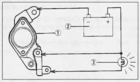
I’ll show you how to conduct each of these two tests. Before that, here’s a wiring diagram to show you how the voltage regulator [Component 1] and battery [Component 2] are connected with a load [Component 3] in between:
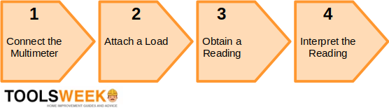
In both (indirect and direct) methods, you will need a voltmeter or multimeter to test a Kawasaki voltage regulator, whether indirectly through the battery or directly. Here’s an outline of the procedure we will follow:
Testing a Kawasaki Voltage Regulator Indirectly
Follow these steps to test a Kawasaki voltage regulator indirectly through the battery:
Step 1: Connect the Multimeter
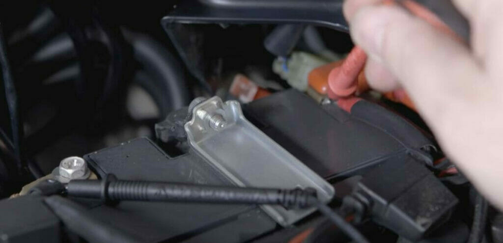
Connect the multimeter’s positive (red) lead to the battery’s positive (+) terminal and its negative (black) lead to the battery’s negative (-) terminal.
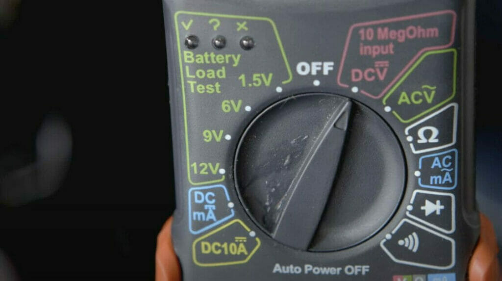
Set the multimeter to read DC volts.
Step 2: Attach a Light Load
You must attach a light load to test the voltage regulator while it’s in use.
Simply turn the ignition partially to only turn the headlight on.
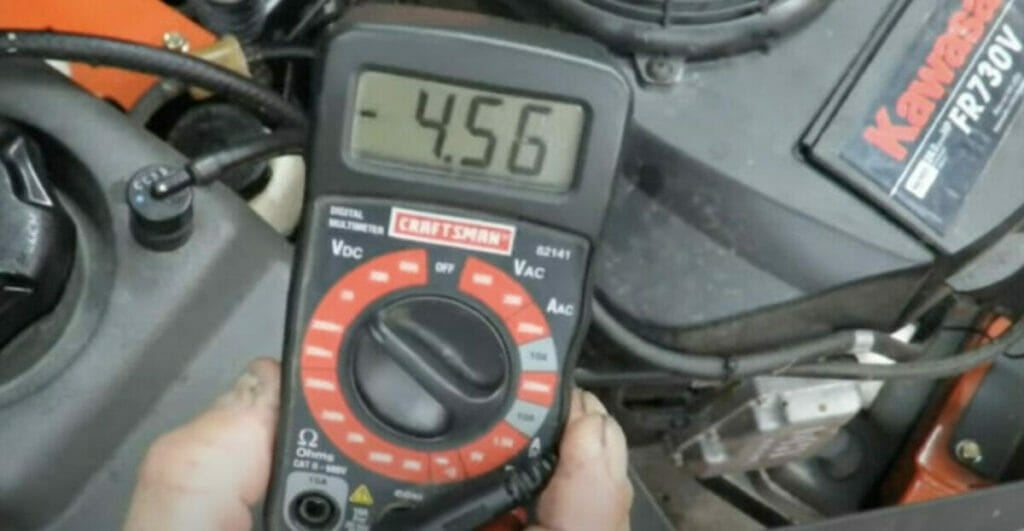
Step 3: Obtain a Reading
Set the multimeter to read in volts and attach the probes.
Step 4: Interpret the Reading
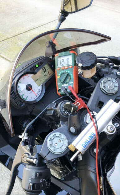
The reading should be close to 12 volts.
For example, 12.2 volts would be a good reading.
If it’s close to 12 volts, then the battery is good. But when you turn the engine on, the reading should go higher. It should be somewhere between 13 and 14.5 volts. The reading on full throttle should be close to 14.5 volts.
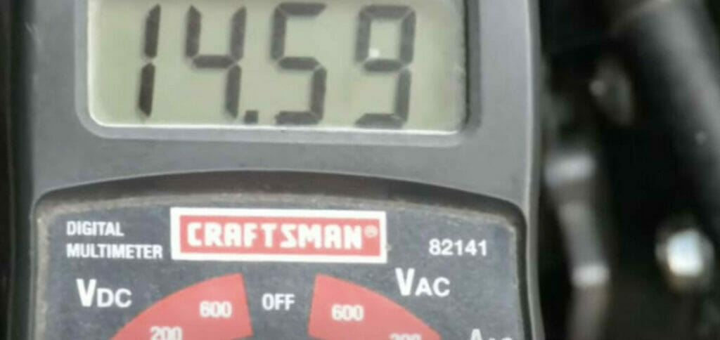
For example, a reading of 14.7 volts would be good.
If it does that, then the voltage regulator is fine. If the voltage does not rise, the voltage regulator is likely to be worn out or damaged. You will have to replace it.
Testing a Kawasaki Voltage Regulator Directly
Follow these steps to test a Kawasaki voltage regulator directly:
Step 1: Connect the Multimeter
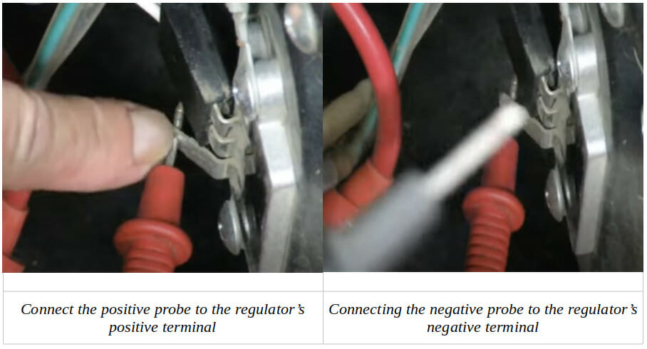
Connect the multimeter’s positive (red) lead to the regulator’s positive (+) terminal and its negative (black) lead to the regulator’s negative (-) terminal.
Set the multimeter to read AC volts.
Step 2: Attach a Light Load
You must attach a light load to test the voltage regulator while it’s in use.
Simply turn the ignition partially to only turn the headlight on.
Step 3: Obtain a Reading
Set the multimeter to read in volts and attach the probes.
Step 4: Interpret the Reading
Start the engine and take a reading.
The reading this time should be constant. If it remains constant, the voltage regulator is doing its job fine. If it fails to remain constant, it might be damaged and need to be repaired or replaced.
The generator brushes should also give a reading. If they don’t, you have worn-out brushes that need replacing.
Testing the Kawasaki’s Charging System
More thorough testing of the Kawasaki charging system involves testing the resistance between different terminals.
Step 1: Remove the Fuel Tank
First, you must remove the fuel tank to access the voltage regulator.
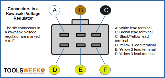
Step 2: Disconnect Connector A from the Regulator
Disconnect Connector A from the regulator.
It’s the left one on the top row in the diagram below, marked as A and connected by a white lead.
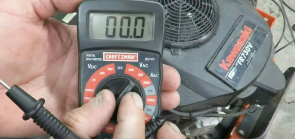
Step 3: Connect the Multimeter to the Regulator
Set the multimeter to measure resistance and connect it to the regulator, as indicated in the table below.
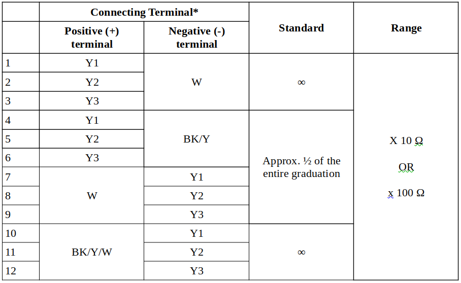
Step 4: Measure the Resistance of Respective Diodes
Measure the resistance across the respective diodes in both directions.
Step 5: Interpret the Measured Resistance
The measured resistance should be small in one direction and at least 10 times greater in the other.
If the resistance of any two wires (W or Y) is small (or large) in both directions, the regulator is not operating as designed and must be replaced.
More about the Kawasaki Voltage Regulator
How the Kawasaki Voltage Regulator Works
A Kawasaki voltage regulator is a crucial component in the electrical circuitry of modern bikes.
If you frequently have problems with your Kawasaki voltage regulator or are a motorcycle mechanic, you might be interested to learn more about how it works or is supposed to.
Parts of the Voltage Regulator Circuit
The main parts of the voltage regulator circuit you will need to be familiar with are:
- Battery
- Carburetor
- Charging coil
- Electric starter
- Flywheel
- Fuse
- Ignition coils
- Key switch
- Spark plugs
- Voltage regulator
They are all interconnected, forming a circuit. The fuse is normally 20-25 amps.
The Kawasaki Voltage Regulator
The Kawasaki voltage regulator is so-called because it regulates or rectifies the voltage.
As its name suggests, it regulates or rectifies the alternator stator coil’s voltage. It ensures the voltage remains within a tolerable limit, usually around 14.5 volts. The alternator stator coil produces an electrical charge at AC voltage. So, the voltage regulator also converts from AC to DC current, as other motorcycle parts and accessories rely on it.
The alternator stator normally connects with the regulator through three wires, although some bikes have a simpler design with only two. In the case of three, two wires would come from the stator, and one wire would be hooked from the starter to the voltage regulator.
Common Causes of Failure
The voltage regulator on a Kawasaki motorcycle can fail due to several reasons.
Common causes of failure are excess heat and the battery.
Excess Heat
Manufacturers attach the voltage regulator in various places on a motorcycle.
Adequate ventilation is essential, as it can heat up easily if located near the radiator or along a section that impedes airflow. Usually, however, it overheats when it draws too much current or if the heat sink weakens and fails to absorb enough heat.
The voltage regulator can eventually fail if it overheats regularly.
Battery
The battery is another common cause of voltage regulator failure.
The ground connection, in particular, must be reliable. A weak ground connection can cause the regulator to operate hotter than normal. A worn battery connection can also cause it to fail altogether.
References
Haynes. Haynes service & repair manual: Kawasaki ZX600, ZX750. Haynes. 1999.
Regulator Rectifier. https://www.ebay.co.uk/itm/155531596485
Video References
Carl
Moto Travel USA
Sartin Garage
Yadzz MotoVlog