5 min read
How to Best Wire an Amp Meter on a Tractor

Having problems wiring an amp meter on a tractor?
As someone who grew up on a farm and then became an electrician, I can say amp meter wiring is an issue many surprisingly struggle with. Once you know how an amp meter works, wiring it is easy.
Pay attention to the basics, and you should be fine.
Materials Required
Get these things ready to wire an amp meter to a tractor.
- 8 AWG (10.0 mm2) wires
- Wire cutting tool
- Ammeter
Analog or Digital Ammeter?
You must choose between an analog or a digital ammeter.
Most older tractor owners go for the analog meter, but digital multimeters are becoming increasingly popular. These can be a good choice because digital ammeters show the exact readings. Also, most digital ammeters serve the dual function of ammeter and voltmeters. You decide!
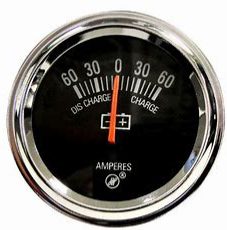
You might also want to verify if your tractor is compatible with the type of ammeter you are planning to use. Usually, a standard 12 V 60 A ammeter should work well on any tractor.
Getting Started
Step 1: Start with disconnecting the battery ground cable.
Step 2: Connect an 8 AWG (10.0 mm2) wire from the battery terminal or the alternator. It is typically connected to the left terminal of the ammeter.
Step 3: Connect the starter solenoid terminal to the ammeter with an 8 AWG (10.0 mm2) wire. It is typically connected to the right terminal of the ammeter.
Step 4: Connect the ammeter to the existing instrument panel lighting circuit.
Step 5: Reconnect the ground cable of the battery.
Step 6: Engage the starter and check if it shows a positive charge. If it does, reverse the connections on the back of the ammeter.
How Does an Analog Ammeter Work?
The ammeter consists of a movable coil connected duly with the input terminals. This coil generates a magnetic field when current passes through it. This magnetic field, in turn, responds with a second field, resulting from a permanent magnet placed at the center.
Spring is set to counteract the torque generated by the interaction of these two magnetic fields. Hence, when the current increases, the spring also stretches according to the magnitude of the input current. A fine needle attached to the coil shows the reading.
Wiring should be done in such a way that it ensures that the maximum current flows through the ammeter circuit.
Some tractor owners also believe it is more convenient to abandon the ammeter and use a voltmeter instead.
Nevertheless, these devices utilize an analog-to-digital converter (ADC) along with complex circuitry, translating the voltage to a digital code.
Understanding the circuit design is very important to figure out how to wire an amp meter on a tractor.
You should also have a basic idea about how an analog-to-digital converter works. An ADC follows a particular sequence to achieve this conversion. First, the ADC samples the analog signal and quantifies it to determine the resolution of the signal. Finally, it sets binary values, sending them to the system to read the digital signal. The sampling rate and resolution are the two most important aspects of the ADC. (1)
However, the basic idea of an ADC may be of little relevance when you need to wire an ammeter to the tractor electrical circuit. Your focus should be on ensuring that the wires are connected to the right terminals. Also, grounding the device is of crucial importance.
Wrong connections can blow up the fuse or make the ammeter non-functional. It can also cause serious injuries or damage the electrical circuit altogether.
What is Most Important to Know About Connecting an Ammeter to The Circuit?
Wiring an amp meter on a tractor is not rocket science. You should never connect the ammeter in parallel. It would form a short circuit path, and as a result, the device will burn out. Also, a series connection ensures a minimum voltage drop across it.
Furthermore, the parallel connection ensures that the circuit offers the least resistance. (2)
You must pay close attention to the circuit diagram and connect the wires to the terminals accordingly.
Take a look at some of our related articles below.
- What gauge wire from battery to starter
- What wires go to the starter solenoid
- Voltage drop test alternator
References
(1) analog-to-digital converter – https://www.arrow.com/en/research-and-events/articles/engineering-resource-basics-of-analog-to-digital-converters
(2) parallel connection – https://www.britannica.com/technology/parallel-circuit
Video Reference