10 min read
How is an Ammeter Connected to a Circuit (Guide)
Hey everyone, I’m here today to talk about something that might seem intimidating initially, but I promise it’s not as complex as it sounds. We will dive into how an ammeter is connected to a circuit.
If you’re wondering what an ammeter is, it’s a tool that measures the flow of electrical current in a circuit. It’s a crucial part of understanding and working with any electrical system, whether you’re a DIY enthusiast, a student, or a professional electrician.
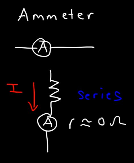
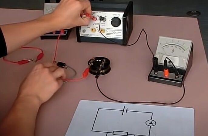
Ammeters are connected in series within a circuit. In most cases, the ammeters are placed after a resistor. Thus, the application of the wires should have a specific direction: the positive terminal of the ammeter should be set to the end of the resistor. The negative terminal should connect to the wire closest to the circuit.
So, grab your tools, and let’s get ready to learn something new about the electrifying world of circuits and how an ammeter becomes a part of it. Let’s get started.
Understanding the Role of Ammeters in Electrical Circuits
Let’s dive into ammeters and why they’re crucial for electrical circuits.
An ammeter is a tool that measures how much electricity is flowing through your wires. It’s essential for anyone working on electrical projects.
An ammeter in your toolkit is essential for any electrical project, from a simple DIY to more complex setups. Why? Because it helps you ensure that your circuit is working as it should.
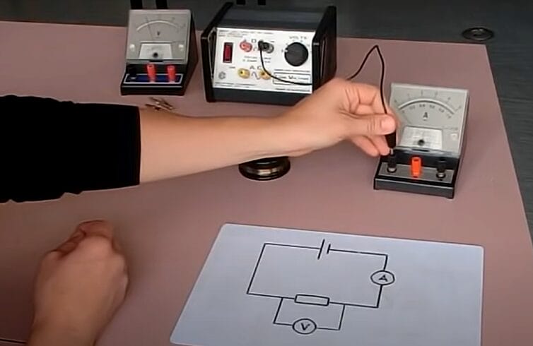
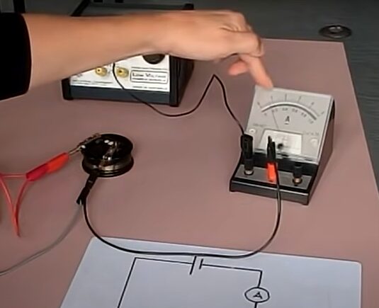
When you’re connecting an ammeter, it’s pretty straightforward. It has to go in series with your circuit. This means it becomes a circuit part, just like any other component.
One thing I appreciate about ammeters is their precision. They tell you the current without messing with the circuit itself. Knowing the exact current in my projects, whether a small DIY fix or a more complex setup, helps me ensure everything is safe and working as it should.
So, I ensure my ammeter is right there whenever I start an electrical project. It’s a simple tool, but it makes a huge difference.
How Do You Connect an Ammeter to a Circuit?
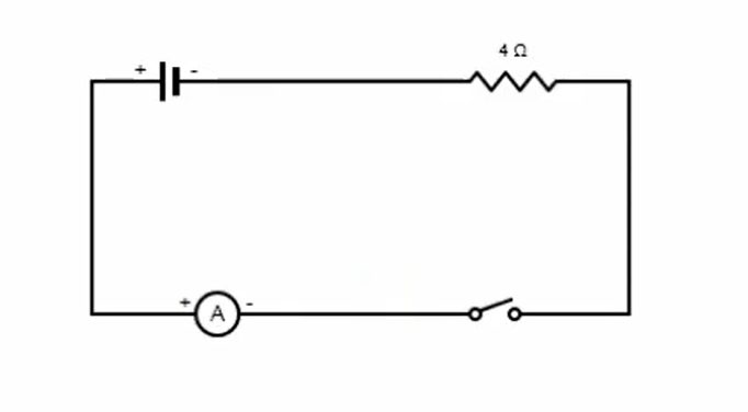
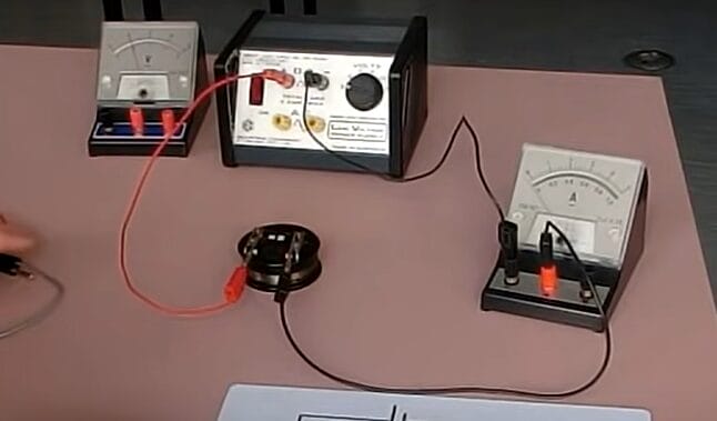
Connecting an ammeter to an electrical circuit is quite simple if one follows some specific steps.
Step 1: Start with the Power Source
Your first move is to start at the negative end of the power source.
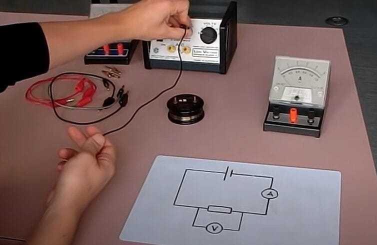
Step 2: Connect to the Ammeter
From there, attach this negative end to the negative side of the ammeter.
Step 3: Add the Resistor
Next, you’ll need to connect the positive side of the ammeter to one end of the resistor.
Step 4: Complete the Circuit
Then, take the other end of the resistor and link it back to the positive side of the power source. This creates a complete path for the electricity to flow.
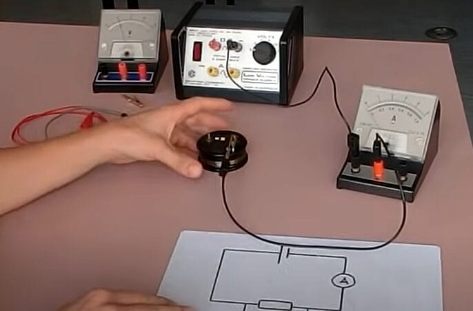
Step 5: Ensure a Closed Circuit
Now, you’ve got a circuit where the electricity flows from the negative end, through the ammeter, through the resistor, and back to the positive end.
Step 6: Safety Check with Low Voltage
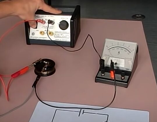
Always start with a low voltage when testing the circuit to ensure everything works correctly.
Note: After applying the device, you can power the meter and the circuit. To disconnect the ammeter, you must first cut the circuit’s power.
Comparing Ammeters with Voltmeters and Multimeters
Let’s discuss the differences between ammeters, voltmeters, and multimeters. Understanding these differences helps you pick the right tool for the job.
Ammeters are like the specialized tools in your toolbox. They’re designed to measure current, specifically. An ammeter is your go-to instrument when you want to know how much electrical current flows through a circuit. It’s connected in series with the circuit and has low resistance to ensure it doesn’t alter the current flow. Use an ammeter when current measurement is your primary goal.
Voltmeters, on the other hand, measure voltage. Think of them as the level of your construction project. They determine the electrical potential difference between two points in a circuit. Unlike ammeters, voltmeters are connected in parallel. They have high resistance, which is great because it prevents them from drawing significant current from the circuit. Choose a voltmeter when you need to check voltage levels, like when troubleshooting power supply issues.
Multimeters are the Swiss Army knives in the electrical world. They can measure current, voltage, and often resistance, too. They’re versatile and convenient, especially for quick diagnostics or when dealing with various measurements. However, remember that while they’re jacks-of-all-trades, they might not be as precise in specific measurements as dedicated instruments. Turn to a multimeter for general-purpose electrical testing or when you need multiple measurements from a single device.
Knowing which tool fits the task is key to any successful project. Stay safe and measure wisely!
Troubleshooting Tips for Ammeter Connections
Let’s dive into some handy troubleshooting tips for connecting an ammeter. Getting this right can save you a ton of time and prevent pesky issues that can turn a simple task into a headache.
| Problem | Possible Cause | Solution |
|---|---|---|
| Ammeter Not Reading | Incorrect Connection (Parallel/Series) | Connect ammeter in series. Check connections. Correcting this to a series connection solved the issue. |
| Ammeter Reading Too High | Low Range Setting | Switch to a higher range on the ammeter. |
| Ammeter Reading Fluctuates | Loose Connections | Fluctuating readings in my early days taught me to double-check for loose connections. |
| Ammeter Damaged After Connection | Connected in Parallel | Always connect the ammeter in series. |
| Inappropriate Range Setting | Ammeter Not Reading | Adjust the ammeter to a suitable current range. |
| Short Circuit | Ammeter Reading Too High | A high ammeter reading during a renovation project indicated a short circuit, which we quickly addressed. |
| Variable Load | Ammeter Reading Fluctuates | Observe load changes; consider stabilization. |
| Need for Calibration | Ammeter Reading Fluctuates | Calibration became key when I worked on precision equipment, as an uncalibrated ammeter led to fluctuating readings. |
| Exposed to High Current | Ammeter Damaged After Connection | Ensure the current is within the ammeter’s capacity. Use a surge protector. |
Remember, when in doubt, always refer to the ammeter’s manual and follow the safety instructions. And don’t hesitate to consult a professional if things seem out of your depth. Stay safe and happy measuring!
Frequently Asked Questions
- Can An Ammeter Be Connected In Parallel?
- Connecting an ammeter in parallel is a big mistake. It’s designed for minimal resistance, so a parallel connection could lead to a short circuit and damage the ammeter. Always go series.
- What Happens If I Connect The Ammeter Backwards?
- The ammeter might give you a negative reading if you connect it backward. It’s not the end of the world, but it’s better to connect it correctly to get accurate, positive readings.
- Why Does An Ammeter Have Low Resistance?
- Ammeters have a low resistance to ensure they don’t significantly affect the current they’re measuring. High resistance would alter the current flow, skewing your measurements. Low resistance keeps things accurate.
- How Do I Choose The Right Ammeter For My Circuit?
- Check the current range you expect in your circuit and choose an ammeter that can handle that range comfortably. It’s all about matching the tool to the task.
- Is It Safe To Use An Ammeter On Any Circuit?
- Ensure the ammeter’s current range exceeds the circuit’s expected current. Always follow proper safety protocols – turn off the power before connecting or disconnecting the ammeter.
References
Organizations:
- Institute of Electrical and Electronics Engineers (IEEE). https://www.ieee.org/
- National Association of Certified Home Inspectors (NACHI). https://www.nachi.org/
Books:
- “The Art of Electronics” by Paul Horowitz and Winfield Hill. https://www.booktopia.com.au/electrical-safety-code-manual-kimberley-keller/book/9781856176545.html
- “Electrical Engineering 101: Everything You Should Have Learned in School… but Probably Didn’t” by Darren Ashby. https://www.barnesandnoble.com/w/electrical-engineering-101-darren-ashby/1100694184
Website Resources:
- All About Circuits. http://allaboutcircuits.com/
- Electronics Hub. http://electronicshub.org/
- SparkFun Electronics. http://sparkfun.com/
Video References:
NCERT OFFICIAL
The Organic Chemistry Tutor
LDSreliance
Felix Olsson