5 min read
How are Voltmeters Connected in a Circuit?
Have you ever wondered how voltmeters are connected in a circuit? I will cover this and more below.
Voltmeters measure the potential difference between two spots in a circuit. You might find that an alternating current (AC) or a direct current (DC) can flow within a circuit. However, that doesn’t affect the voltmeter’s performance. It can detect potential difference values in any device, resistor, or power source. Many people wonder how they are installed in a circuit.
Voltmeters are connected in a parallel arrangement within a circuit. Due to their high resistance, they do not allow electricity to flow within them. Thus, with the parallel arrangement, the voltmeter doesn’t block the current’s flow within the circuit.
I’ll go into more detail below.
Getting Started
In complex circuits, electrical items must be placed in a certain arrangement to allow different parts to remain active or powered off.
The arrangement is divided into three categories:
- Parallel
- In series
- A mix of both
A parallel circuit allows for two items connected to a single power source to remain active or shut off regardless of one another. Suppose you have two lights connected to the same power source in a parallel arrangement. If they are both deactivated, and you open one light, the other will remain off. If they are both on and you close one light, the other will stay on.
A series circuit allows all items connected within it to activate and deactivate simultaneously. That means that in a room with lights connected to the same power source and arranged in series, they will activate and shut off by the use of a single switch at the same time.
The third category has several electrical items arranged in series and other groups in parallel structures. This is mostly used in complex circuits.
How is a Voltmeter Connected to a Circuit?

Voltmeters measure the difference in electric potential between two points within a circuit.
Depending on the complexity of the circuit, one can measure different points and receive different results, as opposed to the ammeter. Every item in a circuit creates its own electric potential difference when electricity flows within it.
The same thing applies to groups of items connected in series. Suppose that there are three lamps connected in series. The first lamp will have different potential from the second and third lamps. Similarly, the second lamp will have a different potential from the third lamp.
Suppose you measure the difference in electric potential of the three lamps as a group. In that case, you will find that the result will be the sum of the electrical potential differences of each lamp.
Remember that any instrument that measures voltage is installed in series within the circuit. These devices are designed with the maximum possible resistance. They do not draw the electricity flowing to themselves and show false measurements of total amperage and voltage circulating within the circuit.
Thus, the voltmeter is connected in parallel.
Why Does the Voltmeter Connect Like That?
There are two reasons why voltmeters are connected in parallel:
- Resistance
- Potential difference
I’ll explain further.
1. Resistance
Each item in a circuit carries a certain amount of resistance.
Voltmeters are designed to carry the most resistance possible (i.e., greater than the sum of the resistance of all items within a circuit).
To understand the logic behind the phenomenon, I should explain how the current flows within a circuit.
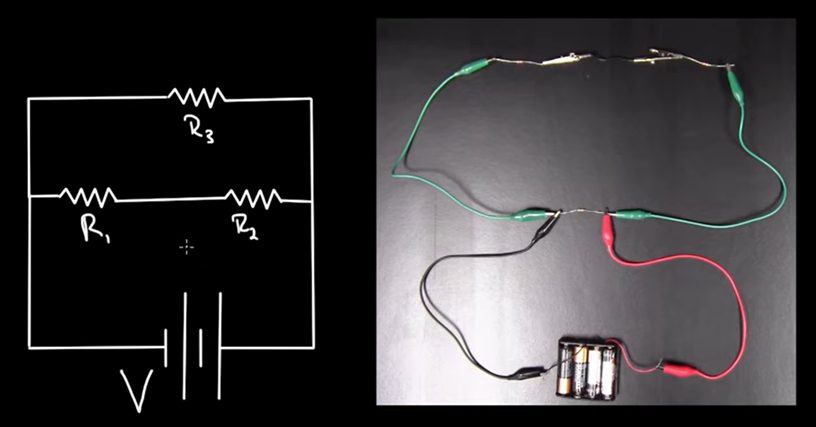
Think of an electric circuit with many branches in a parallel arrangement. Each branch has its own resistance that differs from the others, and the electrical current will flow in each branch. However, more current will stream through the branch with the least resistance compared to the other branches.
Thus, the voltmeter will connect in parallel so that no electrical current (in an ideal scenario) will pass through it.
2. Potential Difference
Voltmeters measure potential differences between spots in the circuit.
The spots the voltmeters can measure are usually the poles of a battery or the ends of a branch or resistor. Both the poles and the ends of the items are on the edges of the devices.
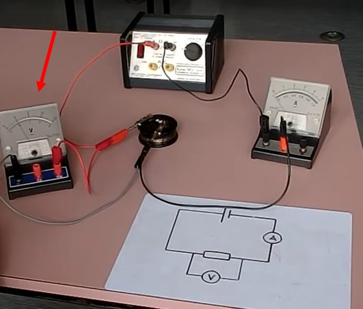
The cables should connect:
- One-on-one side of the pole, branch, or resistor
- And the other cable on the other side of the device
That creates a parallel arrangement.
Video References
khanacademymedicine
Doc Schuster
Felix Olsson