6 min read
How is a Voltmeter Connected in a Circuit?
When you need to test the voltage in a circuit, a voltmeter is the right instrument.
You could also use a multimeter incorporating a voltmeter, but you would still set it to read the voltage as a voltmeter does. However, how do you connect it to a circuit? Where or how should you connect the two probes? Specifically, whether it should be connected in series or parallel. This article tells you how to connect a voltmeter to a circuit.
In General, a voltmeter is always connected in parallel in a circuit across the component, load, or power source to be tested. However, be sure to observe the polarity.
I also explain why it should be in parallel, mention a couple of good practices, and give you some additional related information about voltmeters.
The Voltmeter
Why would you need to connect a voltmeter to a circuit?
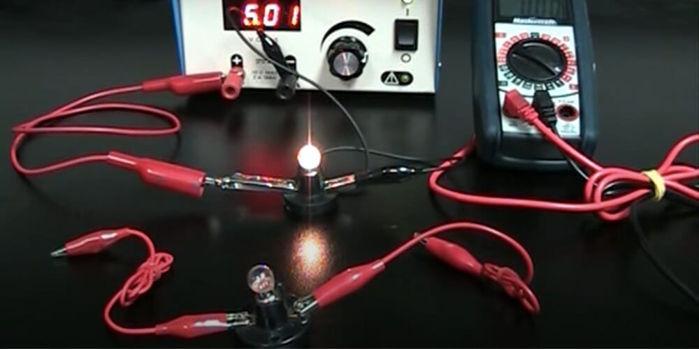
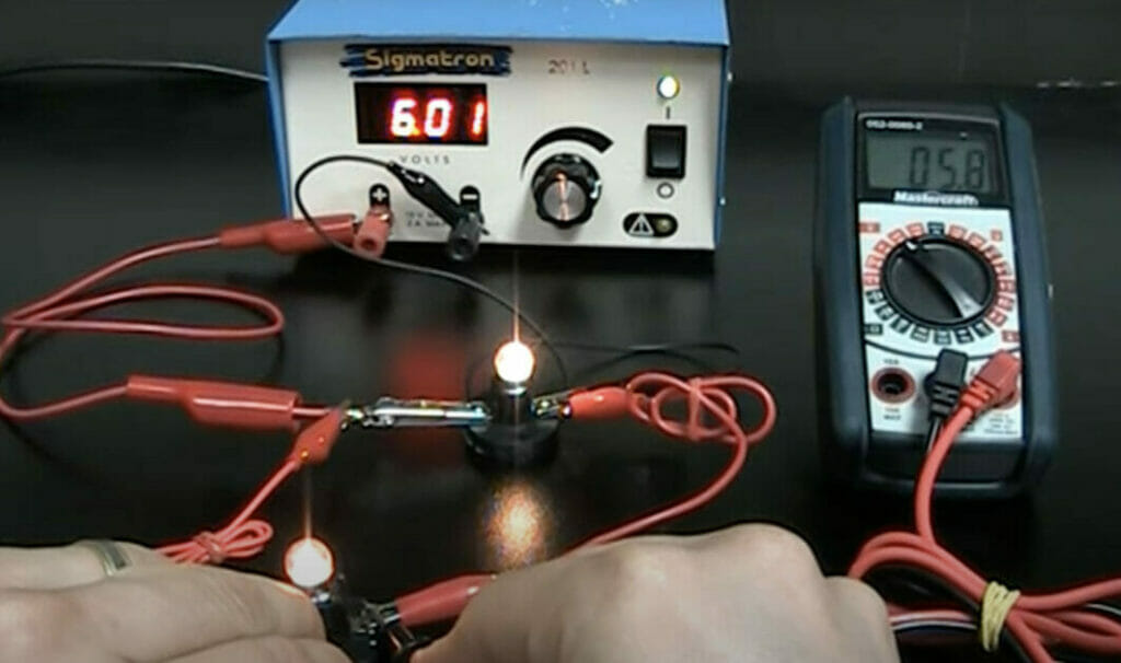
A voltmeter is a measuring instrument that measures the voltage (or potential difference) across the two points being measured. For example, it may be the voltage across a component, the load, or the power source, such as a battery.
The voltmeter will give the reading in volts (V). If it’s an analog type, the needle will point to a value on a scale; if it’s a digital type, you’ll get a reading on its screen.
There’s more information about voltmeters at the end of the article.
Connecting a Voltmeter
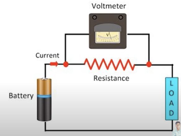
When connecting a voltmeter to a circuit, connect it in parallel.
The two leads or probes from the voltmeter should be connected across the component, load, or power source you’re testing. However, be sure to observe the polarity.
The positive (red) lead should be connected to the positive end or side, and the negative (black) lead to the negative one.
Once connected, the voltmeter will check the potential difference between the two points and give you a voltage reading.
Examples
Let’s look at some examples.
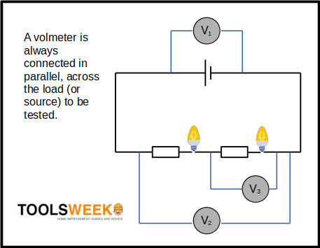
In the above circuit diagram, a pair of light bulbs and resistors are connected in series to a power source. Together, they comprise the total load in the circuit.
I’ve shown three options above for connecting the voltmeter (which is done in parallel):
- Placing the voltmeter in position V1 will test the voltage across the power source.
- Placing the voltmeter in position V2 will test the total load in the circuit, which should be roughly equal to the voltage of the power source.
- Placing the voltmeter in position V3 will test the voltage across one of the light bulbs and the resistor next to it.
RELATED What is a Combination Circuit?
Why Parallel?
You might wonder why a voltmeter is connected in parallel, not in series.
If you connect the voltmeter in series, the voltage (or potential difference) will show as 0 volts and shorten the voltmeter’s terminals. The same current will flow through the voltmeter and the component being tested, which is not what you want.
When the voltmeter is connected in parallel, the current will be varied, but the amount passing through the instrument itself will be small (due to its high internal resistance). The circuit’s constant voltage will thus allow measuring it as accurately as possible.
Good Practices
Setting the Volmeter’s Range
Determine whether you will test AC or DC voltage up to what voltage you need to test. Then set the voltmeter to a larger scale that covers the voltage up to which you’re testing.
For example, if you’re testing a DC 9V battery and can choose from 0-5V, 0-2.5V, 0-10V, 0-50V, and 0-100V, you should set the range to 0-10V. This covers the voltage level from 0 to 9, allowing you to see where the needle points easily.
This only applies to an analog voltmeter, so you don’t need to worry about choosing an appropriate scale if you have a digital one.
Disconnecting the Power
Disconnect or remove the power source from the circuit before connecting the voltmeter, and then reconnect it. This will give you a more accurate reading.
More About Voltmeters
Actual Voltage
One thing to note is that the actual voltage across a component or load will be slightly higher than the voltmeter’s reading. [Gates, 2011]
This is due to the voltmeter’s internal resistance. So when you connect it in parallel with what you’re measuring, the total resistance will be less than the smallest. Usually, a voltmeter’s internal resistance is high enough (~10MΩ) to make this error negligible.
But it might make a difference if you’re trying to measure something very accurately, especially in a high-resistance circuit. If this matters, consider this, or use a high-quality voltmeter with an extra high internal resistance.
Inside a Voltmeter
A voltmeter contains a galvanometer, which is a device that detects current.
It can handle only a certain amount of current because it usually has a low tolerance. A large resistor is, therefore, connected in series with the galvanometer to control the current. It increases the instrument’s overall resistance to accept current within its limit.
As a result, the high internal resistance enables the voltmeter to match the target reading when connected in parallel closely. The discrepancy is minor, but otherwise, the voltmeter accurately measures what it is designed to measure, i.e., the voltage level.
References
Earl Gates. Introduction to electronics. Cengage Learning. 2011.
Video References
Tdphysics
Physics Mentor