6 min read
How to Wire Lights In Parallel with Switch Diagram (Guide)
Two main ways to connect light bulbs are series and parallel connections. Both have their own set of advantages, disadvantages, and uses. Residential circuits used in basic electrical wiring installation are (or should be) connected in parallel. In most cases, switches, outlet receptacles, and light fixtures are linked in parallel to maintain the power source to other electrical devices and appliances through the hot and neutral wire if one fails.
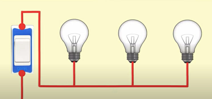
In general, to wire a light in a parallel circuit with a switch, connect the neutral wire to one of the lamp sockets. Connect the Line Wire to the switch terminal and then connect a wire between the 2nd switch terminal and the bulb socket/holders.
In this context, we will learn how to wire lights in parallel with a switch diagram.
Safety Precautions
- Please read all cautions and instructions before beginning with this guide.
- Turn off the power before maintaining, repairing, or installing electrical equipment.
- Never attempt to operate electricity without sufficient training and supervision.
- Work with electricity only in the company of those who have good knowledge, practical experience, and understand how to handle electricity. (1)
- Doing your own electrical work is both unsafe and illegal in certain areas. Before making any changes to your electrical wire connections, contact a certified electrician or a power supply provider.
RELATED What is a Combination Circuit?
Procedures
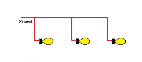
Step 1. Connect the neutral leads of all bulbs and the neutral terminal of the power supply.
Step 2. Connect either one of the switch’s terminals or the power source’s phase terminal.
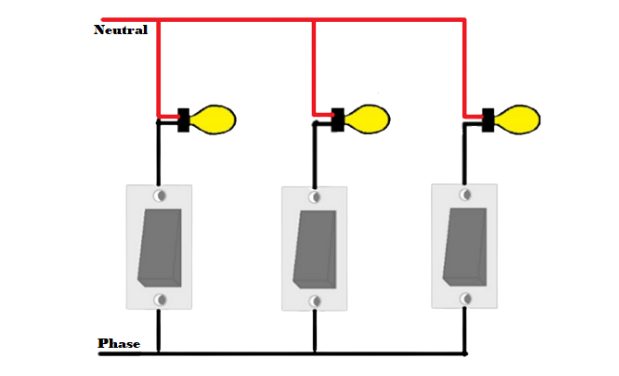
Step 3. Connect each switch’s rest terminal to the rest terminal of each bulb.
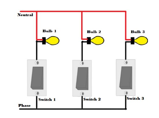
Step 4. Give each switch a name based on the lights it is linked to.
Parallel Connection of Light Switch Wiring
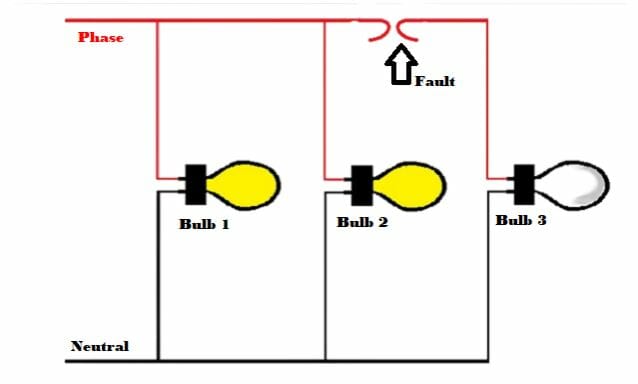
Because the voltage in a parallel circuit is the same at each point, but the flowing current is variable, adding or removing one bulb from the circuit has no effect on the other lamps or connected devices and appliances. In this type of circuit, any number of lighting points or loads may be added (according to the circuit or sub-circuit load calculation) by simply extending the L and N wires to further lights.
As you can see, three lights are linked in parallel here. Each lamp’s neutral is connected and is to be connected to the power source’s neutral. In addition, the phase terminals of each bulb are linked and must be connected to the phase terminal of the power supply. There is no need to apply a higher voltage than the voltage of the individual light when connecting lights in parallel. Using the same voltage as the light switch voltage rating, the lights attached to the circuit in parallel may be powered. The resistance of a single light cannot impact the entire circuit. Higher wattage lighting can shine brighter here. Furthermore, the voltage across each light is the same. However, the current drawn by each bulb is not equal; it is determined by their resistance and watt rating. (2)
Parallel Lamp Connection: Advantages and Disadvantages
Advantages
- Each linked electrical device and appliance is self-contained. In this manner, turning a device on or off does not affect the other instruments or their operation.
- In the event of a cable break or the removal of a lamp, all circuits and related loads will remain operational; in other words, other led lighting and electrical appliances will continue to function normally.
- If more light bulbs are added to the parallel lighting circuits, their brightness will not be diminished (as it occurs only in series lightning circuits). Because the voltage at each point in a parallel circuit is the same. In a nutshell, they get the same power as the source voltage.
- As long as the circuit is not overloaded, it is feasible to add more light fixtures and load points in parallel circuits as needed in the future.
- Adding more devices and components will reduce the total resistance of the circuit, mainly when high current rating equipment such as air conditioners and electric heaters are employed.
- A parallel wiring diagram is more dependable, safe, and easy to utilize.
Disadvantages
- More extensive cable and wire are employed in parallel lighting wiring diagram circuits.
- More current is required when a second light fixture is added to the parallel circuit.
- For DC installation, the battery drains faster.
- Parallel wiring is more difficult to design than series wiring.
Series vs. Parallel Connection
Series Circuit
A basic electrical wiring installation is made of a closed circuit through which direct current flows. A battery is the most basic electrical wiring installation source of DC, and connecting a tiny bulb across the battery’s terminals creates a simple DC Circuit.
However, practical circuits have more components than a single bulb. A Series Circuit has more than one component and is connected end-to-end such that the same current passes through all of them.
Parallel Circuit
When two or more components are linked in parallel, they have the same potential (voltage) difference across their ends. The amount of the potential differences between the components is the same, as are their polarities. The same voltage is applied to all parallel circuit components.
A parallel circuit has two or more routes for the current to flow. All of the features in a parallel circuit have the same voltage. There is only one channel for current to flow in a series circuit. Regarding parallel circuits, there are several paths for current flow.
Take a look at some of our related articles below.
- How to wire lights on a 48 volt golf cart
- How to cap off electrical wires
- What gauge wire for light fixture
References
(1) practical experience – https://medium.com/@srespune/why-practical-knowledge-is-more-important-than-theoretical-knowledge-f0f94ad6d9c6
(2) resistance – http://hyperphysics.phy-astr.gsu.edu/hbase/electric/resis.html