9 min read
How to Test Solenoid with a Multimeter (4-Step Guide)
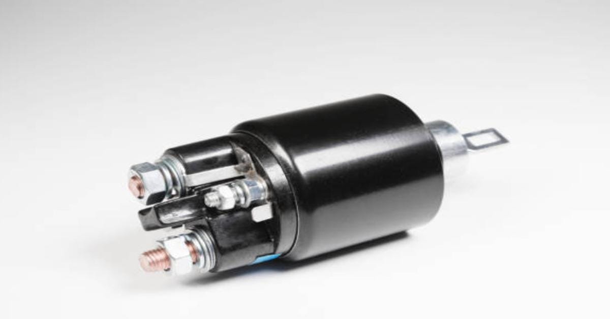
Solenoids, those little magnetic dynamos, are the heartbeats in many of our everyday machines. They’re the unsung heroes in the electrical world, from kickstarting your car to powering heavy machinery.
But what happens when things go haywire, and your solenoid plays hard to get? That’s where we come in with our trusty multimeter.
Quick Summary:
- Step 1: Adjust your multimeter to the ohms setting.
- Step 2: Locate the small coil terminals on your solenoid.
- Step 3: Connect the multimeter leads to the solenoid’s coil terminals and check for resistance readings.
- Step 4: Test for grounding by touching one multimeter lead to a coil post and the other to the solenoid’s bracket.
So, roll up those sleeves, and let’s jump into the fascinating world of solenoids. I’ll walk you through each step, ensuring you’re ready to diagnose and solve like a pro.
Step by Step on Testing Solenoid
Let’s dive into the step-by-step process of testing a solenoid with a multimeter.
Step 1: Setting Up Your Multimeter
- First, we need to set our multimeter to the ohms setting. Look for the symbol that looks like an upside-down horseshoe – that’s our buddy, Omega, indicating ohms.
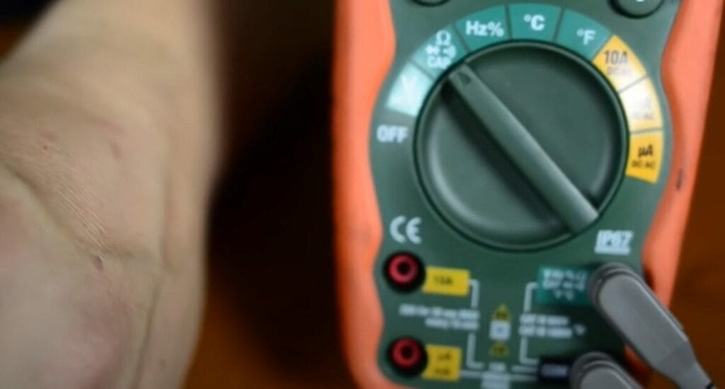
- This setting is perfect for measuring resistance, which is key when testing solenoids.
Step 2: Identifying the Solenoid Posts
- Now, take a look at your solenoid. You’ll see a couple of small posts; these are the coil terminals. This is where the magic happens in a solenoid so we will focus our attention here.
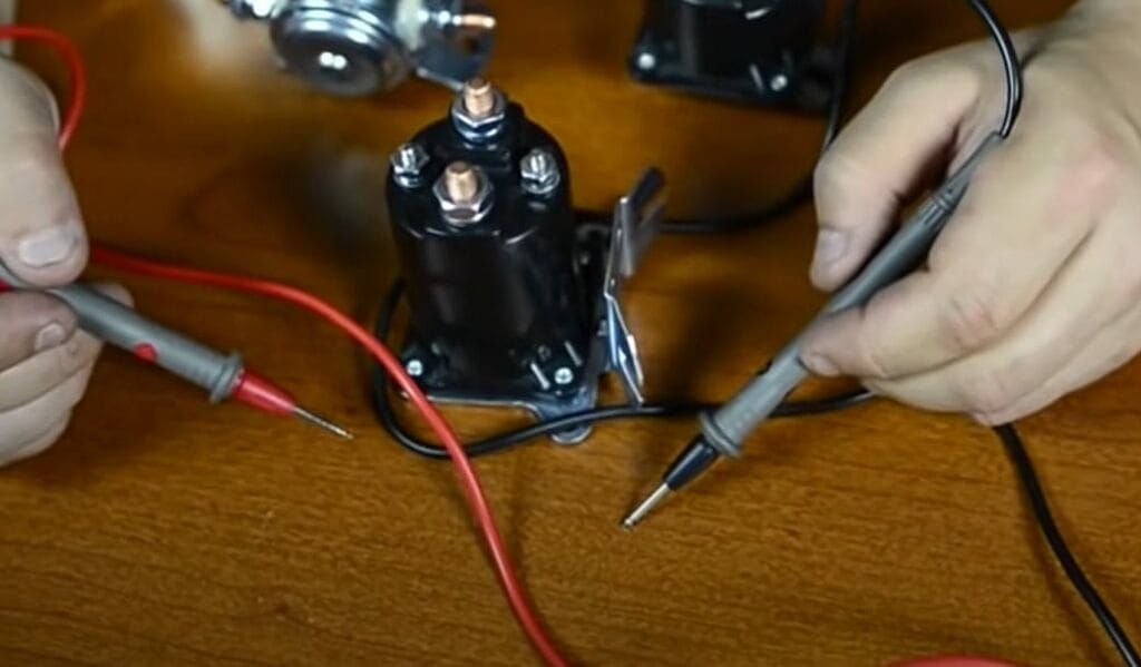
Step 3: Measuring Coil Resistance
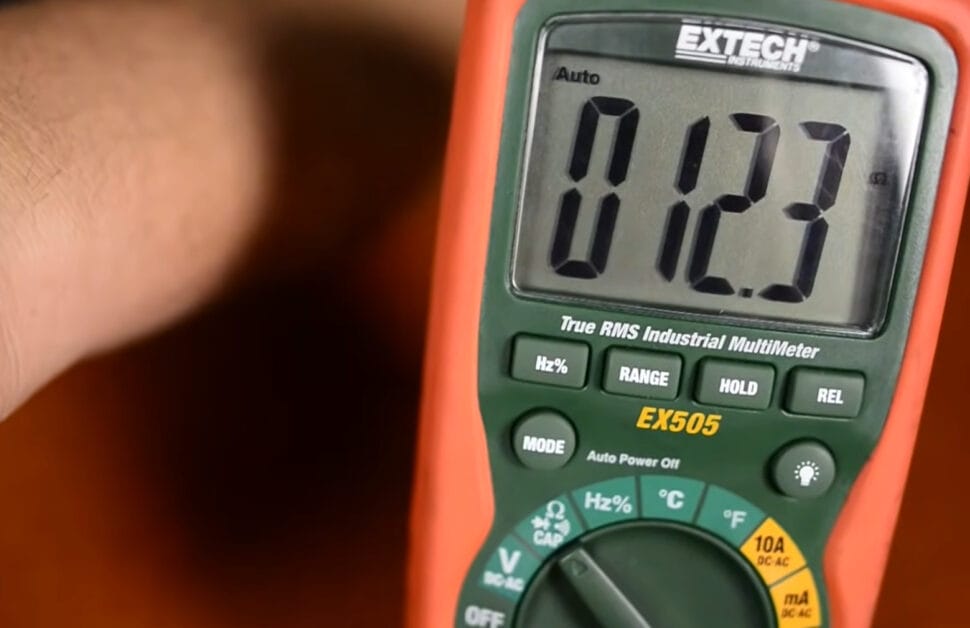
- Attach your meter leads to these small posts. Red to one, black to the other – it doesn’t matter which way round. What we’re doing here is checking the resistance of the coil.
- When I did this, I got a reading of 12.3 ohms. Now, remember, it’s crucial to know the specs of your solenoid. In my case, 12.3 ohms was right in the sweet spot, indicating a good coil.
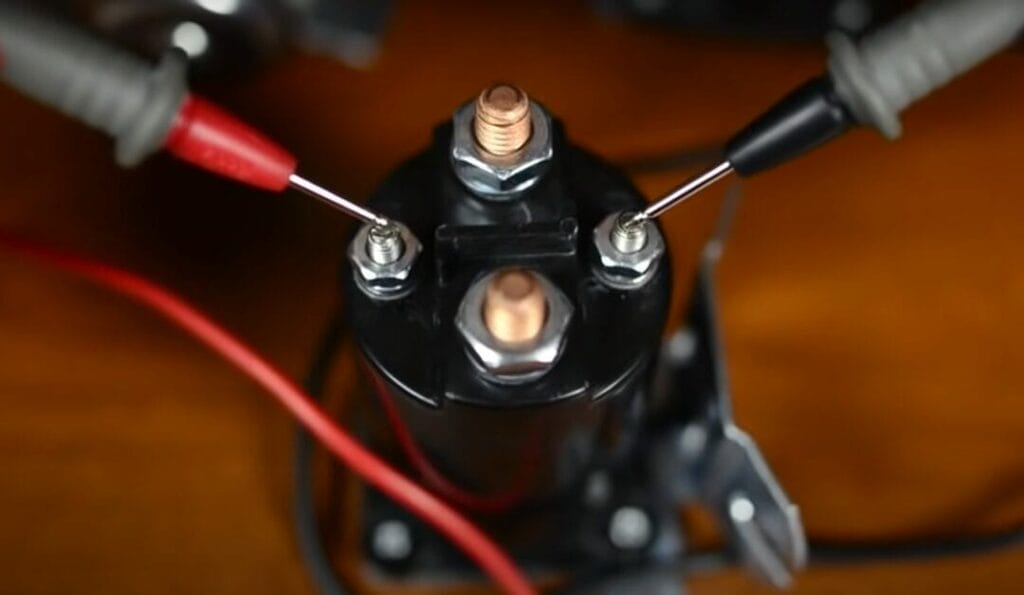
Step 4: Checking for Grounding
- This part is important – we must ensure our coil isn’t grounded. Take one lead and touch it to either of the coil’s posts. Then, touch the other lead to the solenoid’s bracket.
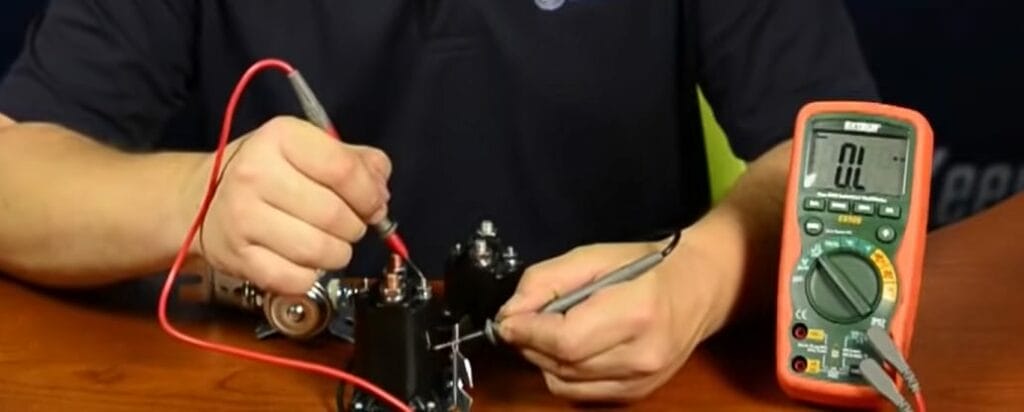
- You shouldn’t get a reading here. Repeat this on the other post. No reading means our coil isn’t grounded, which is exactly what we want.
And there you have it! Testing a solenoid with a multimeter is a piece of cake once you get the hang of it. It’s all about accuracy and knowing what those readings mean. Keep testing, keep learning, and keep those solenoids in tip-top shape!
Troubleshooting Tips for Testing a Solenoid with a Multimeter
Let me walk you through some common hiccups you might run into and how to tackle them. I’ve been down this road a few times and have some tricks to share!
| Common Issue | What’s Happening | How to Fix It |
|---|---|---|
| No Continuity Reading | Your multimeter shows no continuity across the solenoid terminals. | Check the connections. Ensure the probes are firmly attached to the solenoid terminals. Sometimes, it’s just a loose wire. |
| Inconsistent Readings | Readings on the multimeter keep fluctuating. | This could be due to unstable connections. Double-check those probe contacts and make sure they’re not wobbling around. |
| Multimeter Reads Over 1 Ohm | Ideally, it should be between 0 and 1 ohm, but it’s higher. | It might indicate an issue with the solenoid coil. Consider replacing the solenoid if the resistance is too high. |
| Solenoid Not Activating | Even with correct readings, the solenoid doesn’t engage or make a click sound. | This could be a mechanical issue. The solenoid plunger might be stuck, or the spring could be damaged. Time for a closer look! |
| Voltage Issues | The voltage reading is not within the expected range (12-24 volts). | Check the power source. A weak battery or poor connection can cause low voltage. Make sure everything’s juiced up right. |
Don’t hesitate to double-check your connections and settings on that multimeter. And most importantly, keep safety in mind – we’re dealing with electricity here!
Avoiding Common Pitfalls: Solenoid Testing with a Multimeter
Let’s discuss something that can trip you up when testing solenoids with a multimeter. I’ve been there and done that, and let me tell you, even the pros can slip up now and then.
So, I will share some common mistakes to watch out for and how to avoid them.
Mistake 1: Getting Your Settings Mixed Up – Always double-check that your multimeter is set to the ohms setting (the one with the Omega symbol). Once, I was out in the garage, a multimeter in hand, ready to test a solenoid. I was so sure of myself until I realized I had the multimeter set to measure voltage, not resistance. Rookie mistake!
Mistake 2: Probe Placement Woes – Ensure those multimeter leads are firmly attached to the solenoid’s coil terminals. If they’re touching, your readings will be everywhere.
Mistake 3: Ignoring the Importance of a Good Ground – Always test to ensure your solenoid coil isn’t unintentionally grounded by touching one lead to the coil and the other to the solenoid’s body.
Mistake 4: Forgetting to Disconnect Power – Always, and I mean always, make sure the power is off before you start testing. Safety first!
Mistake 5: Misinterpreting the Multimeter Readings -Take your time to understand what the readings mean for your specific solenoid. A misinterpretation can lead you down the wrong path.
Everyone makes mistakes, but the trick is to learn from them. Remember these tips; you’ll be testing solenoids like a pro soon!
Keeping Your Solenoids in Tip-Top Shape: Maintenance Tips You Need to Know
If you’re like me and love keeping your gear in prime condition, you know some maintenance goes a long way. Let’s talk about keeping those solenoids running smoothly. Trust me, a bit of TLC can save you a hassle.
Regular Cleaning is Key – Like any part of your machine, solenoids can collect dust, dirt, and grime. Make it a habit to give them a good, gentle cleaning. Use a soft cloth to wipe away any debris.
Stay Dry, Stay Happy – Moisture is the enemy of electrical components, and solenoids are no exception. Keep them dry to avoid rust and corrosion. It’s like making sure your tools are stored in a dry place.
Check Those Connections – Loose connections can lead to all sorts of trouble. Give those wires and terminals a once-over to ensure everything’s tight and secure.
Listen for the Click – Solenoids should make a distinct click when activated. It might be time for a closer look if you don’t hear this.
Avoid Overheating – Solenoids don’t like getting too hot. If your system is prone to overheating, consider adding some additional cooling, like a fan or heat sink.
Regular Testing – As we discussed, test your solenoid with a multimeter and make this a regular part of your maintenance routine.
Lubrication Can Help – Some solenoids might benefit from lubrication, especially if they have moving parts. Be sure to use the right lubricant, though – you wouldn’t put cooking oil on a squeaky door hinge.
Remember, a little maintenance can go a long way in keeping your equipment running smoothly and efficiently.
Frequently Asked Questions
- Can A Solenoid Be Repaired, Or Must It Always Be Replaced?
- Now, this is a tricky one. Solenoids are usually replaced rather than repaired, especially in automotive contexts. But the real answer depends on what’s wrong with it and how handy you are with tiny mechanical parts.
- What Are The Environmental Factors That Could Affect A Solenoid’s Performance?
- We’re talking temperature, moisture, and maybe even dust and dirt. These elements can all mess with your solenoid’s performance.
- What Is The Lifespan Of A Typical Solenoid?
- It varies based on use, quality, and conditions. Some solenoids can last for years, while others might wear out sooner, especially in harsh conditions.
- Can A Faulty Solenoid Damage Other Components In A System?
- A faulty solenoid causing damage to other parts resembles a domino effect. It’s not common, but it can happen, especially if the solenoid causes electrical issues or mechanical blockages in a system.
References
Organizations:
- Institute of Electrical and Electronics Engineers (IEEE). https://www.ieee.org/
- The International Society of Automation (ISA). https://www.isa.org/
Books:
- “The Art of Electronics” by Paul Horowitz and Winfield Hill. https://artofelectronics.net/
- “Practical Electronics for Inventors” by Paul Scherz and Simon Monk. https://www.barnesandnoble.com/w/practical-electronics-for-inventors-fourth-edition-paul-scherz/1124288626
Website Resources:
- All About Circuits. https://www.allaboutcircuits.com/
- SparkFun Electronics. https://www.sparkfun.com/
- EEWeb. https://www.eeweb.com/
Video References:
Purkeys