6 min read
How to Test a Fan Motor with a Multimeter (Guide)
Single-phase motors are the most prevalent type of fan motor. Other fan motors, such as dual-phase and capacitor start motors, are designed for industrial use and are widespread in factories and warehouses. But they become faulty at some point. Today we’re going to help you test these with a guide that will walk you through how to test the fan motor using a digital multimeter.
In general, you can test a fan motor with a multimeter with these easy steps. First, set the multimeter to ohms and unplug the motor from its power supply to try for a short to ground. Then examine each wire for endless readings. If you receive a reading of 0, you could have a cable problem.
Testing fan motors may be pretty confusing for those with little knowledge. This guide will make testing fan motors simple for you, regardless of your level of experience or the sort of fan motor you’re evaluating.
Main Cause of Fan Motor Problems
Before you begin testing, there is one more item to consider.
A faulty run capacitor is the most common cause of fan motor ‘breakdowns.’ Before you begin testing, always physically inspect the capacitor. Check for ruptured capacitors and capacitors with dents or other defects or faults that must be replaced as soon as possible. If you find such a capacitor, it goes without saying that everything is probably good with the fan motor. However, continue with the testing to ensure that the fan motor is really in good condition. A small problem can cause the entire capacitor to fail.
How to Test a Fan Motor with a Multimeter
#1. Wire Arrangement
Determine which wires you should use for measurement. We’ll go through the wiring configuration now.
Fan motors often have two wires, one brown and one white. Brown cables are connected to the capacitor. The two wires are black and white and need to be connected to the capacitor. We’ll put the wires through their paces based on their functions.
#2. Continuity Test
Examine the motor winding’s continuity from phase to phase with a digital multimeter ( U-V, V-W, W-U ). You must maintain phase-to-phase continuity if the winding is permitted. If any stage fails the continuity test, your motor is most likely burned. The windings should register low but not zero ohms in a three-phase engine. The audible continuity indicator is generally low enough (under 30) to beep.
#3. Power Supply Test
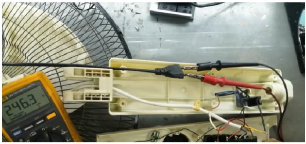
The effectiveness of an electric motor is limited by its power source. You may use the multimeter in the preceding paragraph to test the power supply. The procedure and appropriate ratings for evaluating supply voltage vary on the type of motor. Each motor will have an expected supply voltage range, which you should verify to ensure the cables meet. Your user handbook will provide the required information for testing power and a more detailed specific tutorial. Testing the components of an electric motor may rapidly become intricate, and it’s simple to make mistakes if you’re inexperienced. (1)
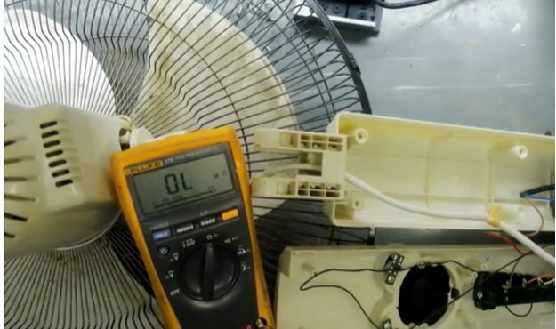
#4. Wired Test
The first set of wires test
Now is the time to put the white–brown and white wires to the test. The white wire is referred to as the run wire.
- Set the ohms setting on your multimeter.
- Touch the white wire with the black multimeter test lead.
- Contact and continue to touch the white-brown wire with the red multimeter probe.
- The values measured in this stage should be in the range of one or two ohms.
- You can set the white-brown wire to the side of the numbers that are correct because you will not need it for today’s test.
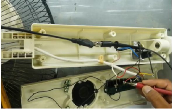
The second set of wires test
The brown wire serves as the start wire, while the black is the standard wire.
- Connect the brown wire’s negative (black) multimeter probe with your multimeter.
- Place the red probe on the white cable.
- Any figure between and around 32 and 40 ohms should be considered an expected value.
The third set of wires test
- Take the red test lead and remove it from the white wire while the negative black multimeter test lead remains on the brown wire.
- Place the red probe on the standard wire now.
During this step of testing, values should be about fifteen ohms.
Fourth set of wires test
- Maintain the red test lead on the black wire while removing the black probe from the white wire.
- Connect the black probe to the white wire.
- This test should be performed without the moving blade.
- The multimeter should read at around twenty ohms.
Aside from the obvious safety concerns about electricity and the danger of damage, it is also to get an accurate measurement. If the blade is rotating while you are measuring, the results will become irregular and exact readings will be unattainable.
Tips
South-wire clips are ideal for this type of work. They will prevent incorrect readings from occurring due to the wire types used in fan motors. You will keep the wire strings by wrapping rubber around the south wires. Here is a collection of short wire names organized by function:
- The white wire is known as the run wire, the brown as the start wire, and the black as the standard wire.
- If your fan motor varies from the setup indicated here, grab the handbook and read it thoroughly.
- If you are still unable to discover or identify a part required for the testing outlined below, look for the fan motor’s metallic plate. That plate has all of the necessary information about the fan motor’s model, manufacturer, voltage, and other critical details. It will allow you to search for additional information online and test this motor with more understanding and precision. (2)
Take a look at some of our related articles below.
- How to test a motor with a multimeter
- How to test a stator with a multimeter
- How to test a car ground wire with a multimeter
References
(1) power source – https://www.sciencedirect.com/topics/
engineering/power-source
(2) metallic – https://www.britannica.com/science/metallic-bond
Video Reference
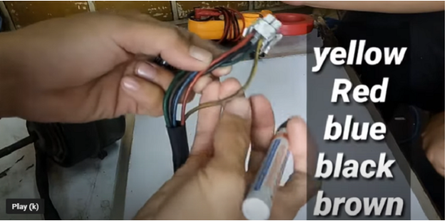
Hi My Name Is André, And I’ve have a Floor Fan. It’s 220 Volts Single Phase
And It’s Has 6 Wires. Red,White,Blue,Brown,Black,Yellow And a Yellow With a Green Strip On Its Side That I Know It’s The Ground. It’s Got a 3 Switch Selector And a capacitor. I Just Want To Know What Colour Wires Go Where
On This Diagram. On The Side Of The Motor Is a Small Sticker That Only Say
It’s a Motor Model ME-35 And below It’s Say 220v-240vac 50hz 70w class 155. Can You Perhaps Help Me On This One.
Thanks