6 min read
How to Test a Motor with a Multimeter? (3 Tests)
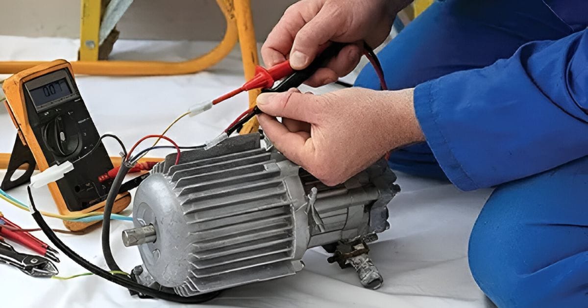
This article shows you how to test an electric motor using a multimeter.
A faulty motor can cause a lot of trouble. You never know when you may have to test it. Usually, a multimeter is all you need to test an electric motor.
You can do 3 tests on an electric motor using a multimeter:
- A voltage comparison test between the capacitor’s terminal and applied voltages by connecting one multimeter’s probes to the power supply wires and another pair to the terminal voltage wires. The latter should be 1.7 times the supply voltage.
- An electrical conduction (continuity) test by connecting 2 multimeters as instructed, which should not beep.
- Motor winding test to check for open or short circuits by connecting 2 multimeters as instructed. They should show a reading of 170 ohms for a 100V motor.
I’ve covered all 3 tests by which we can check an electric motor using a multimeter. We will go into more detail, so let’s get started.
Testing a Motor with a Multimeter
I will show how to conduct the following 3 tests:
- Test 1 will compare the capacitor’s terminal voltage with the applied voltage in 3 steps. Replace the capacitor if this test fails.
- Test 2 will check the electricity conducted through the cable in 3 steps. Replace the affected connector or wire if this test fails.
- In Test 3, we will check the resistance of the motor winding in 4 steps. Have the motor repaired or replaced if this test fails.
Requirements and Setting
You will need 2 multimeters for each of the above 3 tests. You can use the same pair by conducting the tests in turn.
The first test requires setting the multimeter to measure AC voltage, whereas the other 2 tests measure resistance.
Test 1: Compare the Capacitor’s Terminal Voltage with the Applied Voltage
When connected properly, the capacitor’s terminal voltage should be 1.7 times the voltage of the power supply.
The motor is getting the required voltage if you get a reading in line with this ratio (1:1.7). We will use two multimeters for this motor test, which we will call Circuit Tester A and Circuit Tester B.
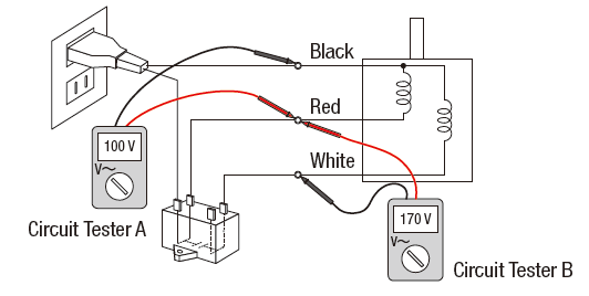
Step 1: Check the Power Supply Voltage with Circuit Tester A
Set the multimeter to measure AC voltage.
As shown in the above diagram, connect the multimeter’s red probe to the red wire and its black probe to the black wire of the power supply wires. These connections are for Circuit Tester A.
You should get a reading equal to the power supply’s voltage. So, if you have a 100 VAC motor, you should get a 100V reading on the multimeter.
Step 2: Check the Capacitor’s Terminal Voltage with Circuit Tester B
We will now use Circuit Tester B to check the capacitor’s terminal voltage.
Attach the second multimeter’s red probe to the red wire and its black probe to the white one. Check the voltage reading on the multimeter.
Step 3: Compare the Two Multimeter Readings
If all the connections are good, you will get a reading for Circuit Test B, 1.7 times the power supply reading on Circuit Tester A.
For example, if you use a 100V motor for this test, you should get a 170V reading on the second multimeter.
The motor works properly if you get a reading 1.7 times the power supply. The motor might have an issue if you don’t get such a reading.
Test 2: Check the Electricity Conducted through the Cable
A faulty wire or connector can be the reason for a bad motor.
So, it’s a good idea to check the wires and connections before suspecting a problem with the motor. This method will check whether the motor circuit is closed or open with a simple continuity test.
Step 1: Cut Off the Power
First, turn the power off because there’s no need for it when doing a continuity test.
Step 2: Make the Connections
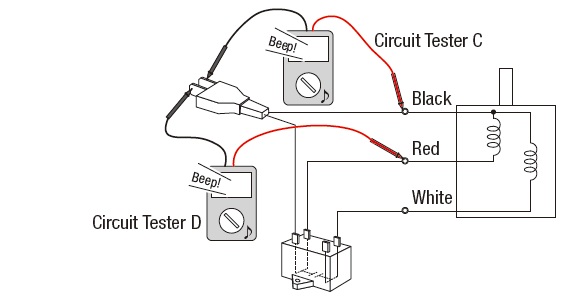
Connect Circuit Tester C and D according to the above diagram.
Connect Multimeter C’s red probe to the black wire and D’s red probe to the red one. Now, connect the remaining two black probes of multimeters C and D to the end of the power cable.
Step 3: Check the Response
The multimeters will beep if there is any break in the circuit.
Note: While testing the wires for continuity, always choose a location that is exposed and close to the motor. When connecting the probes to the wires, connect them securely.
Test 3: Check the Resistance of the Motor Winding
In the 3rd test, we will measure the motor’s winding resistance.
We will then compare it to the original manufacturer’s specified value and evaluate the motor’s condition by comparing the two values.
Step 1: Remove All the Additional Components
First, remove the additional components, such as capacitors and extension cables, from the motor’s circuit.
Step 2: Set the Multimeter
Keep the multimeters set to resistance mode, as in the 2nd test.
Step 3: Connect the Probes
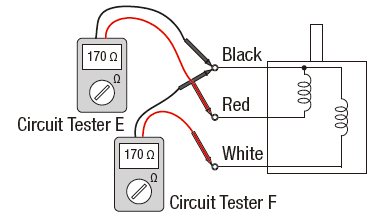
Connect both black probes to the black wire, and connect the red probe of Circuit Tester E to the red wire.
Then, connect Circuit Tester F’s red probe to the white wire. See the diagram shown above.
Step 4: Check and Compare the Readings
Both multimeter readings should be around 170 ohms if it’s a 100V motor.
Sometimes, a reading can be smaller than 170 ohms, like when there is an internal short circuit. However, the readings should be over a few thousand ohms if the windings are broken.
Note that we mentioned a 100V motor above. Regarding other motors, you must find the specified values according to the model. Look at the motor’s label or in its manual, find this information on the internet, or ask the manufacturer. Afterwards, compare the two values.
Mechanical Issues with Motors
If the above 3 electrical tests fail to identify the problem (because all 3 results are positive), it may be due to a mechanical issue.
You won’t need a multimeter, but if you already used one to confirm the capacitor, wiring, and motor winding are all fine, it would be the next thing to check.
For example, a motor’s operation can be affected by a technical problem such as a faulty ball bearing. This can happen as a result of excessive axial or radial load. You might have to test for these kinds of issues, too. Follow these steps:
- Step 1: First, remove the gear head and the motor.
- Step 2: Then, turn the shaft clockwise and counterclockwise.
- Step 3: While rotating the shaft, if you hear abnormal friction or a sound, it is a signal for misalignment or damage. In this case, you might have to replace the motor’s bearings.
References
Website Resources: