9 min read
How to Test a Diode with a Multimeter (5 Easy Steps)
Diodes are the unsung heroes in our electronic devices. They’re the gatekeepers, ensuring current flows in the right direction and keeping our gadgets running smoothly.
But what happens when things go haywire, and you suspect a diode is to blame? That’s where your trusty multimeter comes in. Here are the steps to test a diode:
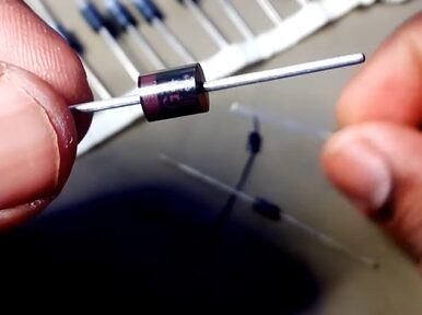
- Step 1: Identify Diode Terminals
- Step 2: Set the Multimeter to Diode Test Mode
- Step 3: Test in Forward Bias
- Step 4: Test in Reverse Bias
- Step 5: Interpret the Readings
I will walk you through the ins and outs of testing diodes in this guide. Whether you’re troubleshooting a home project or satisfying your curiosity about how things work, knowing how to test a diode is a handy skill in your toolbox.
Understanding and Testing Diodes: Identifying Anode and Cathode
Picture this: a diode is like a one-way street sign for electric current, ensuring it flows in just one direction. These little guys are everywhere – in your car’s radio, those nifty little gadgets you love to tinker with, and even in big stuff like solar panels.
Before we get our hands dirty with testing, knowing who’s in the diode family is super important. Diodes have two terminals – the anode (+ve) and the cathode (-ve).
And here’s a little trick to tell them apart: look for the color band. This band is like a secret code; it marks the cathode. No band? That’s your anode.

Diode Testing with a Digital Multimeter
I will show you how to test a diode with a digital multimeter and let me tell you, it’s a game-changer. I’ve been through my share of electronics projects, and this trick has saved me more time than I can count!
Step 1: Identify Diode Terminals
- First, identify the cathode and anode sides of the diode. This is crucial for accurate testing.
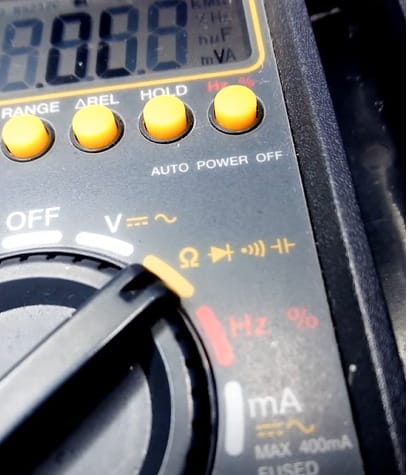
Step 2: Set the Multimeter to Diode Test Mode
- Rotate the central knob of your multimeter to align with the diode symbol. This sets the multimeter to diode test mode, which supplies a current of about 2mA.
Step 3: Test in Forward Bias
- Connect the multimeter’s red probe to the anode and the black probe to the cathode.
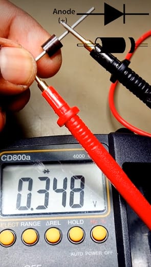
- Observe the voltage reading. A healthy silicon diode should read between 0.6 to 0.7 volts. For a germanium diode, expect a reading between 0.25 and 0.3 volts.
Step 4: Test in Reverse Bias
- Now, reverse the connections – red probe to the cathode and black probe to the anode.
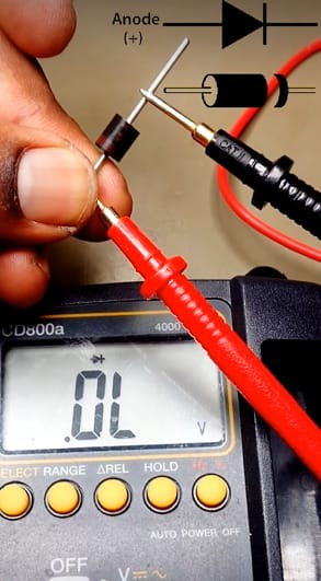
- A healthy diode will prevent current flow in this setup, and the multimeter should show ‘OL,’ indicating an open circuit.
Step 5: Interpret the Results
- If the multimeter displays values significantly different from the expected range in either test, it suggests a problem with the diode.
- No current flow (open circuit): Indicates an open diode, similar to an off switch.
- Zero voltage drop across the diode: Suggests a shorted diode, where the diode allows current to pass freely.
Follow the steps, and you’ll be a master at diagnosing diode issues in no time!
RELATED Multimeter Diode Symbol (Guide)
Diode Test Analysis
Understanding how to analyze the results of a diode test using a digital multimeter is an essential skill in electronics.
Whether you are troubleshooting a circuit, working on a DIY project, or professionally engaged in electronics repair, knowing how to interpret the readings from diode testing can be crucial.
- Forward-Biased Test: When testing a diode in forward-biased condition, look for low resistance on the meter. This indicates the diode is functioning correctly.
- Reverse-Biased Test: In reverse-biased conditions, high resistance on the meter is a sign of a properly working diode.
- High Resistance in Both Conditions: If the meter shows high resistance in both forward and reverse-biased conditions, the diode will likely open and malfunction.
- Low Resistance in Both Conditions: The diode is likely shorted and defective if you observe low resistance in both testing modes.
In summary, the key to diode testing with a multimeter is understanding resistance readings in both forward and reverse-biased conditions to determine the diode’s condition.
Comparison with Other Testing Tools
Let’s get more specific about the other tools used for diode testing besides the multimeter and compare them in detail:
| Tool | Multimeter | Specific Diode Testers | Oscilloscope |
|---|---|---|---|
| Ease of Use | User-friendly and straightforward. Ideal for beginners and pros alike. | Slightly more specialized but still quite user-friendly. | Requires technical knowledge and experience to operate effectively. |
| Specificity | Good for general diagnostics. Identifies basic diode functionality. | Designed specifically for diodes, offering more detailed diagnostics. | Offers in-depth analysis, showing how a diode performs under actual operating conditions. |
| Cost | Generally affordable. A staple in most electronic toolkits. | Typically more expensive than a multimeter but more focused on functionality. | Significantly more expensive; considered a high-end electronic testing tool. |
| Versatility | Highly versatile – measures voltage, current, resistance, and more. | It was primarily focused on diode testing, with limited versatility. | Extremely versatile; can measure and visualize a wide range of electronic signals. |
| Learning Curve | Easy to learn and use. | Similar to a multimeter, with some additional features specific to diodes. | A steep learning curve requires an understanding of electronic waveforms and signals. |
| Availability | Widely available and common in most electronics toolkits. | Less common than multimeters, found in specialized electronics kits. | Not typically found in a standard toolkit; more common in professional or advanced hobbyist settings. |
| Accuracy | Highly accurate for basic diode functionality tests. | Offers more precise measurements specific to diodes, such as breakdown voltage. | Provides detailed and highly accurate measurements of diode performance over time. |
While multimeters are the go-to for their versatility and ease of use, specific diode testers offer more detailed diagnostics, which is especially beneficial for specialized applications. On the other hand, oscilloscopes are more suited for advanced users who need to visualize and analyze the diode’s performance in a circuit.
Avoiding Common Diode Testing Pitfalls: Tips and Tricks for Accurate Multimeter Use
Now, I’ve been around the block a few times with multimeters and diodes, and let me tell you, it’s easy to slip up if you’re not careful. So, let’s talk about some common diode testing mistakes and how to avoid them. Trust me, I’ve learned these lessons the hard way, so you don’t have to!
Getting the Multimeter Setting Wrong: I remember this one time I was helping a buddy out in his garage. We were testing diodes, and he had his multimeter set to measure current instead of voltage. Whoops! The thing is, using the wrong setting can give you all sorts of wacky readings. Always double-check that your multimeter is set to the diode test mode – it usually has a diode symbol or is marked with ‘V’ for voltage.
Mixing Up the Probes: It sounds simple, but mixing up the probes is like putting your shoes on the wrong feet – it just doesn’t work. The black probe should go to the cathode (-ve), and the red one to the anode (+ve). I’ve seen folks do it the other way around and then scratch their heads when the readings are off. Remember, the color band on the diode usually indicates the cathode.
Misinterpreting the Readings: This one’s a classic. You get a reading and think, “What in the world does that mean?” For instance, a 0.6 to 0.7-volt reading for a silicon diode is A-OK, but anything significantly higher or lower can mean trouble. And if you’re testing a germanium diode, expect something around 0.25 to 0.3 volts. Anything outside these ranges, and you might be dealing with a faulty diode.
Testing Under Load: Here’s a pro tip: don’t test diodes while they’re still in the circuit and under load. You’re likely to get some confusing results. Always remove the diode from the circuit if possible, or at least ensure the power is completely off.
Overlooking Physical Damage: Sometimes, the problem is as clear as day. I’ve seen visibly damaged diodes – we’re talking cracks, burns, you name it. Always give the diode a good once-over before you even start testing. Physical damage is a surefire sign that it’s time for a replacement.
Remember these tips; you’ll be testing diodes like a pro in no time. Stay safe, and happy tinkering!
Frequently Asked Questions
- Can I Test a Diode Without Removing It From the Circuit?
- Ideally, remove the diode from the circuit for accurate testing. If that’s not possible, at least ensure the power is off and understand that your readings might not be 100% reliable.
- Is There a Way to Test Zener Diodes?
- You’ll need a power source that can supply a voltage higher than the Zener voltage. Connect the Zener diode in reverse bias with the power source and measure the voltage across it. If it’s close to the Zener voltage rating, your diode works its magic just fine.
- Is It Possible to Repair a Faulty Diode?
- Diodes are pretty much ‘replace, don’t repair’ components. If a diode is faulty, it’s best to replace it with a new one that matches the specifications of the original.
- What Does a ‘0L’ or ‘1’ Reading Indicate When Testing a Diode?
- In diode test mode, this usually indicates no connection or an open diode. It means the current isn’t passing through the diode in the tested direction. If you see this in both directions, the diode will likely open or be damaged.
RELATED Multimeter Diode Symbol (Guide)
References
Organizations:
- Institute of Electrical and Electronics Engineers (IEEE). https://www.ieee.org/
- The Electronics Industries Alliance (EIA). https://en.wikipedia.org/wiki/Electronic_Industries_Alliance
Books:
- “The Art of Electronics” by Paul Horowitz and Winfield Hill. https://artofelectronics.net/
- “Practical Electronics for Inventors” by Paul Scherz and Simon Monk. https://www.barnesandnoble.com/w/practical-electronics-for-inventors-fourth-edition-paul-scherz/1124288626
Website Resources:
- All About Circuits. https://www.allaboutcircuits.com/
- Electronics-Tutorials. https://www.electronics-tutorials.ws/
Video References:
ELECTRO MAX CREATION