4 min read
Multimeter Diode Symbol (Guide)
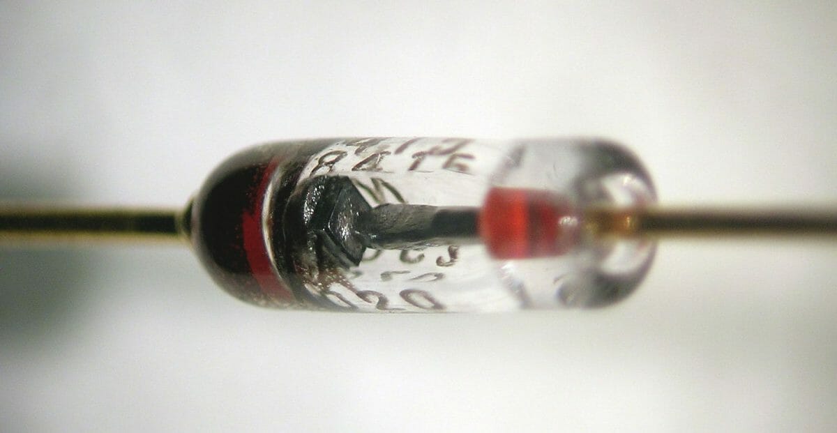
A diode test is the most efficient and relevant way to test if your diodes are in good or bad condition. A diode is an electrical instrument that allows the conduction of current in a direction. It has cathode (negative) and anode (positive) ends.
A multimeter on the other hand is a measuring instrument that can be used to measure resistance, voltage, and current. The multimeter symbols located on it help in performing its different functions. It also has a test lead attached to it. Check the full list here.
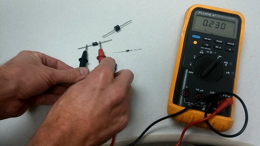
In short, to test a diode you’ve to do the following steps. First, turn the dial of the multimeter to the diode test symbol and turn off the power to your circuit. Next, connect the probe tips of the test leads of the multimeter with the diode. The negative lead to the negative (cathode) end of the diode and the positive lead to the positive (anode) end of the diode, this is the forward bias. Then you’d get a reading on your multimeter. A typical reading for a good silicon diode is between 0.5 to 0.8Volts and a good germanium diode is between 0.2 to 0.3Volts. Reverse the leads, and touch the diode in the opposite direction, it should not bring out any reading but OL on the multimeter screen.
In our article, we’ll further discuss how to test a diode using a multimeter.
Multimeter Diode Symbol
The diode symbol in circuits is generally represented by a triangle, with a line across the vertex of the triangle. This is different on the multimeter, most multimeters have the diode check mode and to perform a diode check one has to turn the dial of the multimeter to the diode symbol on the multimeter. The symbol for a diode on a multimeter looks like an arrow pointing towards a vertical bar, which has a line continuously going out of it.
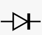
There are several multimeter symbols on every multimeter which have designated functions, examples are Hertz, AC voltage, direct current, capacitance, ohm, and diode test, among others. For the multimeter diode symbol, the arrow indicates the positive side while the vertical bar indicates the negative side.
Diode Tests
A diode test is best done by measuring the voltage drop in the diode when the voltage across a diode permits the natural flow of current which is the forward bias. There are two methods used for diode tests using a digital multimeter, they are:
- Diode Test Mode: This is the best and the most used approach for diode tests. It is a feature already present among the multimeter symbols.
- Resistance Mode: This is an alternative method used if the multimeter does not have a diode test mode.
Diode Test Procedures
- Turn the dial of the multimeter to the diode test symbol on the multimeter and turn off the power to your circuit
- Bring in contact the probe tips of the test leads of the multimeter with the diode. The negative lead to the negative (cathode) end of the diode and the positive lead to the positive (anode) end of the diode, this is the forward bias
- Then you will get a reading on your multimeter. A typical reading for a good silicon diode is between 0.5 to 0.8Volts and a good germanium diode is between 0.2 to 0.3Volts (1, 2)
- Reverse the leads, and touch the diode in the opposite direction, it should not bring out any reading but OL on the multimeter screen.
Wrapping Up
When the test gives a reading for the forward bias it shows that the diode allows current to flow through in a direction. During reverse bias when the multimeter displays OL which means overload. A good multimeter displays OL when a good diode is reversed biased.
References
(1) silicon – https://www.britannica.com/science/silicon
(2) germanium – https://www.rsc.org/periodic-table/element/32/germanium