14 min read
How to Use a Multimeter (Basic Guide for Beginners)
Let me tell you, a multimeter is like a superhero in your toolbox.
Below, I’ll walk you through how to make the most out of this dynamo of a tool. From checking out if there’s juice in your wires to figuring out why your gadgets give you the silent treatment, a multimeter is your best bud.
Let’s dive in and get our hands dirty!
What is a Multimeter?

A multimeter is a versatile tool for diagnosing and troubleshooting various electrical problems. It’s not just about checking whether outlets work or your appliance has conked out.
Think of it as your electrical detective, uncovering mysteries in circuits and components. Here are some diverse scenarios where a multimeter proves invaluable:
- Solar Panel Systems: Check the output of solar panels to ensure they’re delivering the right voltage.
- Automotive Repairs: Diagnose car battery issues or check the electrical system in your vehicle.
- Computer Hardware: Troubleshoot power supplies in computers.
- Home Theater Systems: Verify connections and power outputs in complex audio-visual setups.
- HVAC Systems: Test thermostats and other components in heating and cooling systems.
These examples illustrate the multimeter’s role in various settings, from home electronics to more specialized applications like solar energy or automotive repairs.
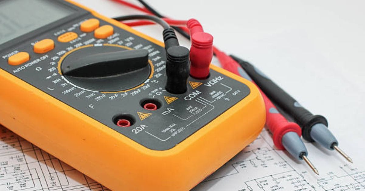
Multimeter Parts
A digital multimeter is made up of four main sections:
Display
This is the pane that displays the electrical measurements. It has a four-digit display with the capacity to show a negative sign.
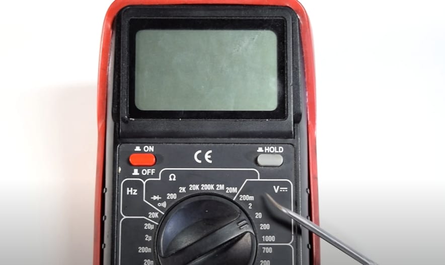
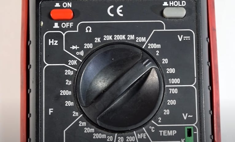
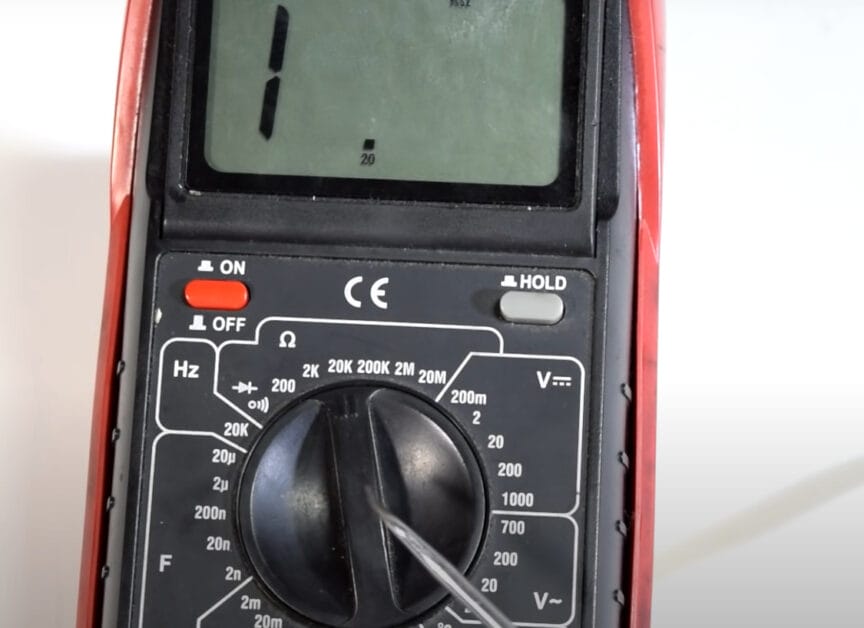
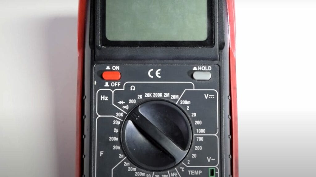
Selection Knob
It’s a round dial on which you can select the type of electrical unit you want to measure. You can choose from AC volts, DC volts (DC-), amps (A), milliamps (mA), and resistance (Ω).
On the selection knob, a diode sign (triangle with a line on the right side) and a soundwave symbol indicate continuity.
Probes
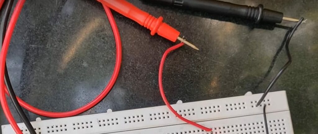
These red and black wires are used to test electrical components physically—a pointed metal tip on one end and a banana plug on the other.
The metal tip probes the tested component while the banana plug connects to one of the multimeter’s ports. You can use the black cord to test Ground and neutral connections, while the red wire is typically used to test hot terminals.
Ports
Multimeters commonly include three ports:
- COM (-) – stands for common and where the black probe is usually plugged. A circuit’s Ground is usually always linked to it.
- mAVΩ – is where the red probe is conventionally plugged to monitor voltages, resistance, and current (up to 200mA).
- 10A – is used to measure currents greater than 200 mA.
Measuring Voltage in Household Electronics
An old lamp seemed beyond repair until my multimeter identified a faulty plug. It was a quick replacement, and it was as good as new.
How to Check: Test your lamp’s outlet and plug it into an AC voltage multimeter to diagnose issues. Here are the steps:
Step 1: Set your multimeter to AC voltage.
Step 2: Check the adapter’s output by connecting the probes to the adapter’s terminals. If the reading matches the adapter’s output specification, the adapter is fine.
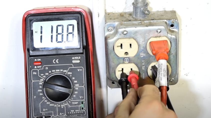
Step 3: Switch the multimeter to DC voltage. Test the lamp’s switch by placing probes on either side of the switch. A voltage reading when the switch is ‘on’ indicates the switch is functioning correctly.
Measuring Battery Voltage
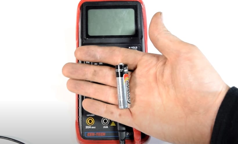
A dead remote control on movie night led me to test the batteries with my multimeter. The problem was just drained batteries, which were easily fixed.
How to Check: Use your multimeter on the DC voltage setting to check the remote control batteries. Here are the steps:
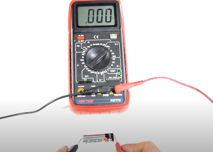
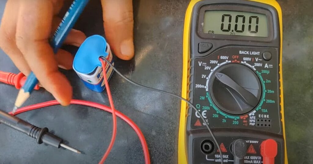
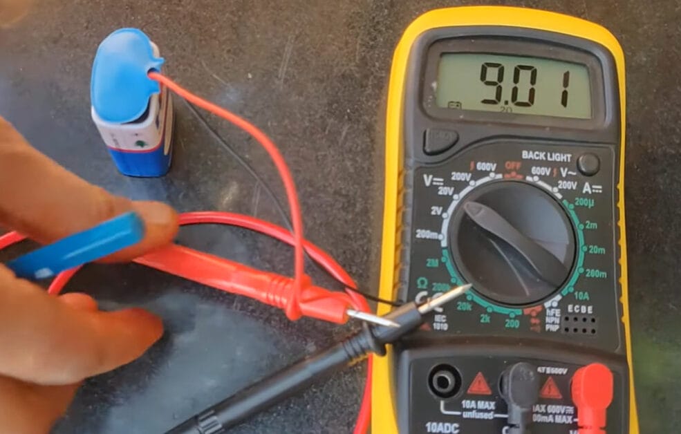
Step 1: Set your multimeter to the “2V” DC setting.
Step 2: Place the probes on each battery’s terminals. A reading below the battery’s rated voltage (usually 1.5V for AA batteries) means it’s time to replace them.
Measuring Circuit Voltage in a DIY Project
Building a custom LED light setup required precise voltage measurements to avoid damage, made possible with my multimeter.
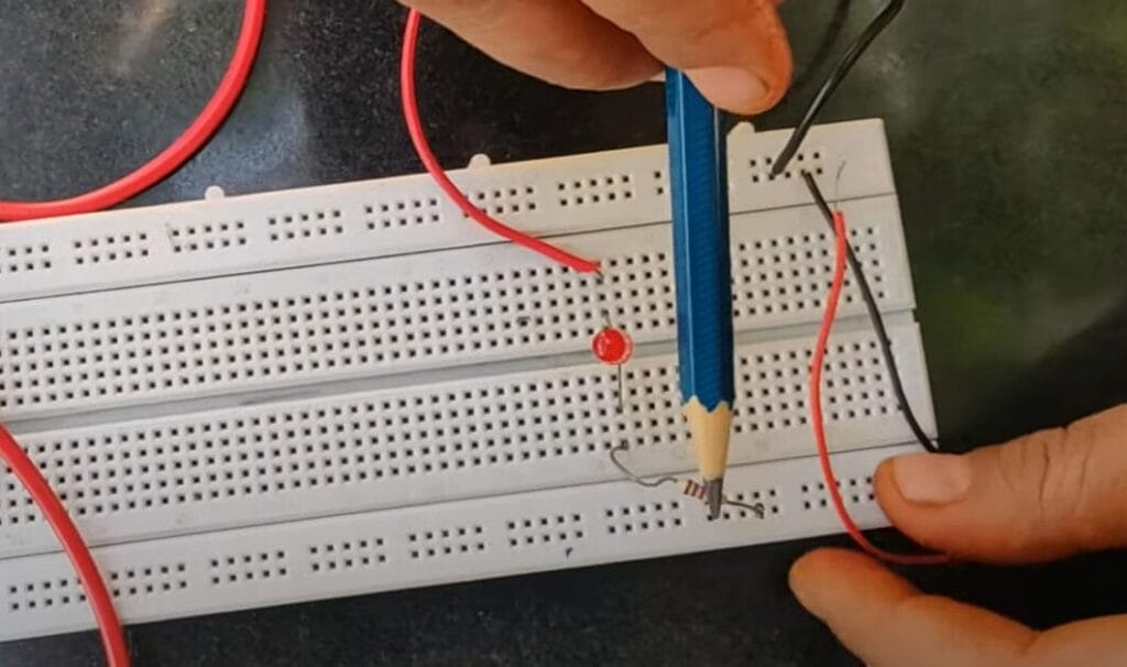
How to Check: Measure each LED’s voltage with a multimeter to ensure they receive the correct amount. Here are the steps:
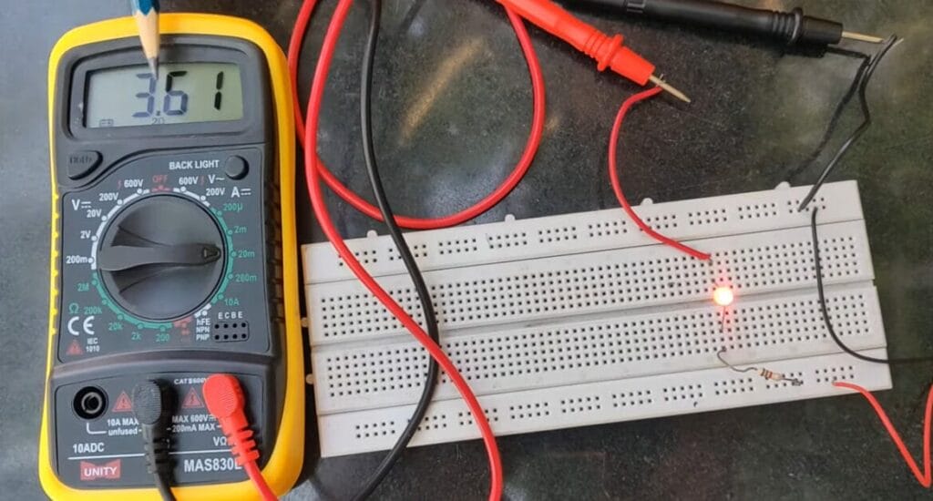
Step 1: Set the multimeter to “20V” DC with the circuit powered.
Step 2: Measure across the LED to see the voltage drop. This helps ensure your LED receives the correct voltage.
Measuring Current in a Circuit
When my coffee maker stopped working, measuring the current flow with my multimeter led me to a faulty wire, which was quickly mended.
How to Check: Insert your multimeter in series with your appliance’s circuit to check for current flow issues. Here are the steps:
Step 1: Disconnect the power wire from your circuit component.
Step 2: Connect the multimeter in series (breaking the circuit flow).
Step 3: Set to measure current. A reading within the expected range confirms your circuit’s current draw is as planned.
Measuring Resistance in Electronic Components
A malfunctioning circuit in a weekend project was due to a faulty resistor, which was identified by comparing resistance readings on my multimeter.
How to Check: Test each resistor’s resistance against its color code with a multimeter to find discrepancies. Here are the steps:
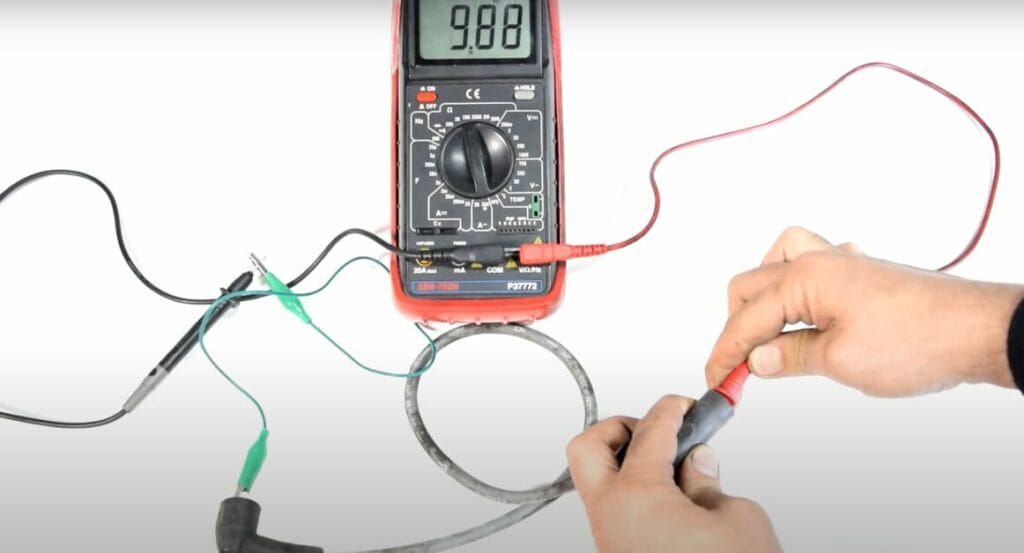
Step 1: Set the multimeter to resistance mode. Choose an appropriate range.
Step 2: Touch the probes to the resistor’s leads. The reading should match the resistor’s value, helping you identify or confirm its resistance.
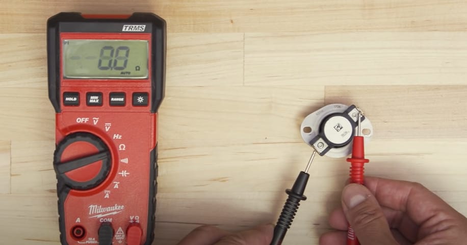
Continuity Test in Wiring and Circuits
A non-functioning speaker in my car’s new sound system was due to a loose wire, which was found using the multimeter’s continuity test.
How to Check: Use the continuity test function on your multimeter to trace speaker wire issues in-car audio systems. Here are the steps:
Step 1: Switch the multimeter to continuity mode.
Step 2: Touch the probes to both ends of the wire.
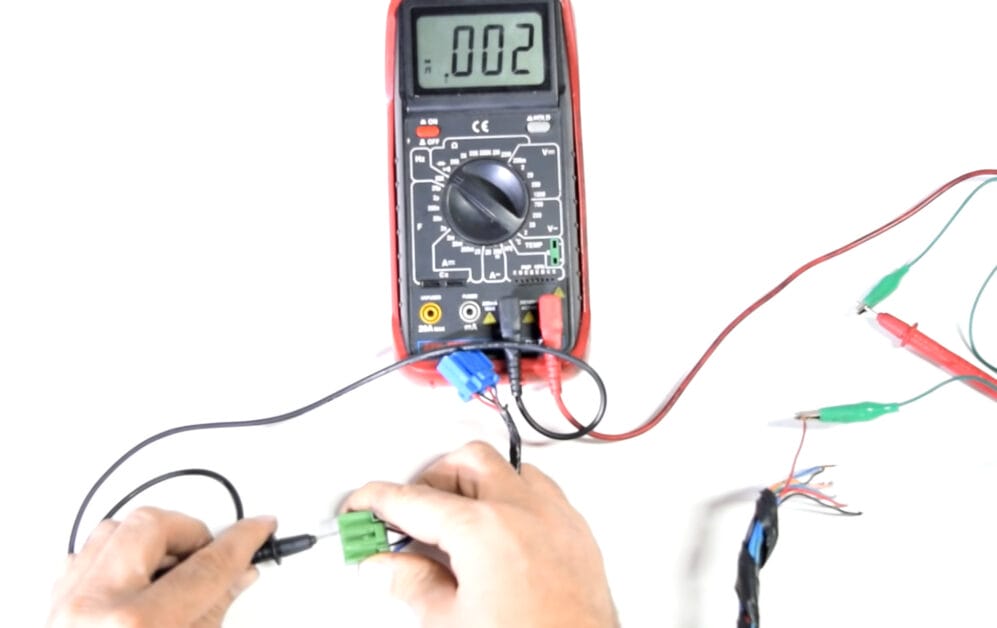
Step 3: A beep confirms the wire is intact, while no beep indicates a break somewhere along the wire.
Each scenario demonstrates how a multimeter can be an indispensable tool, guiding through various electrical challenges easily and efficiently.
Advanced Multimeter Tips: Navigating Complex Measurements
Alright, for all you advanced DIYers and tech enthusiasts, let’s level up your multimeter game with some advanced tips and tricks.
Here’s a table that breaks down some complex scenarios you might encounter and how to tackle them like a pro:
| Challenge | Description | Advanced Solution |
|---|---|---|
| Precision in Crowded Spaces | Measuring in areas with limited space | Use magnetic holders for your probes. They attach to metal surfaces, keeping your hands free and your readings stable. |
| Dynamic Signal Analysis | Dealing with signals that vary over time | Utilize a multimeter with a graphing capability to visually track changing readings, ideal for understanding complex, dynamic systems. |
| Microcurrent Measurements | Accurate readings for very low current | Employ a multimeter with a microampere range for precise current measurements in delicate electronics like sensors or IoT devices. |
| Wireless Monitoring | Measuring in hard-to-reach or dangerous areas | Use a multimeter with remote connectivity. Measure and monitor readings via a smartphone app, ensuring safety and convenience. |
| Harmonic Distortion Analysis | Identifying noise in power lines | Opt for a multimeter with harmonic distortion analysis to identify and measure unwanted frequencies in power lines, crucial for audio equipment and sensitive electronics. |
| Environmental Impact Assessments | Understanding how environment affects circuits | Some multimeters come with integrated humidity and temperature sensors, allowing you to see how environmental conditions impact your electrical systems. |
Remember, with great power (and features) comes great responsibility – always read your multimeter’s manual and understand its capabilities and limitations. Stay safe, and keep exploring!
Multimeter Missteps: Avoiding Common Errors
Using a multimeter seems straightforward, but it’s easy to stumble, especially when you’re new to the game. Let’s clear up some frequent mix-ups and keep your electrical adventures on track.
- Using the Wrong Setting: One of the easiest slip-ups is not setting your multimeter to the right mode. Always double-check if you’re measuring voltage, current, or resistance, and choose the appropriate setting. It’s like picking the right tool for the job.
- Testing Live Circuits: Big no-no here. Testing continuity on a live circuit can damage your multimeter and cause personal injury. Power down before you test – safety first!
- Ignoring Probe Condition: Your probes are in your multimeter’s hands. Frayed or damaged probes can lead to inaccurate readings and are a safety risk. Regularly inspect and replace them if they show signs of wear.
- Overlooking Range Selection: Select the correct range if your multimeter isn’t auto-ranging. Choosing a too-low range can overload your meter, while a too-high range might give you less accurate readings.
- Misinterpreting Readings: Numbers on the screen are only half the story. Understand what those readings mean. A high resistance reading doesn’t always indicate a problem, just like a zero reading doesn’t always mean perfection.
- Forgetting to Zero Out: Short the probes together before measuring resistance and adjust the reading to zero. This ensures more accurate resistance measurements.
- Neglecting Multimeter Calibration: Like any precision instrument, multimeters need regular calibration to stay accurate. It’s easy to forget but crucial for reliable readings.
- Disregarding Environmental Factors: Temperature and humidity can affect your multimeter’s performance. Using it in extreme conditions might skew your results.
- Assuming Continuity Equals Functionality: Just because a circuit has continuity doesn’t mean it’s functioning correctly. Continuity tests for a complete path, not the quality of that path.
- Overreliance on the Multimeter: Remember, a multimeter is a tool, not a magic wand. It can give you a lot of info but can’t replace a thorough understanding of the circuit you’re testing.
Remember, knowing your tool is as important as knowing how to use it. Stay sharp, stay safe!
Frequently Asked Questions
- How Accurate are Multimeters?
- Multimeters vary in accuracy. Generally, digital models are more accurate than analog ones. Check the specifications for accuracy ratings, usually a percentage of the reading.
- When Should I Calibrate my Multimeter?
- Calibration depends on usage and the manufacturer’s recommendations. A good rule of thumb is to calibrate once a year but more often if you use it frequently or in critical applications.
- Analog vs. Digital Multimeters: Which Should I Choose?
- Digital multimeters are easier to read and usually more accurate. However, analog models can be better for detecting rapid voltage changes. It boils down to your specific needs and preferences.
- How Do I Know If My Multimeter is Giving an Accurate Reading?
- Test a known voltage source, like a fresh battery, to check accuracy if in doubt. Regular calibration also helps ensure accurate readings.
- What’s the Significance of CAT Ratings on Multimeters?
- CAT ratings indicate the safety level of a multimeter based on the type of electrical environment it can handle. Higher CAT ratings mean the device can safely measure higher voltages.
- Is It Safe to Test Live Wires with a Multimeter?
- Yes, but only if your multimeter is rated for the voltage you’re testing and follows proper safety protocols. Always use insulated gloves and be cautious.
- Can I Use a Multimeter on Electronics Like Phones and Laptops?
- Yes, but be careful. Use a multimeter with appropriate settings and probes suitable for delicate electronics.
- What’s the Best Way to Store My Multimeter?
- Store your multimeter in a clean, dry place, preferably in a protective case, to prevent dust buildup and accidental damage.
- How Do I Select the Right Probe for My Measurement?
- Use standard probes for most measurements. For specific tasks like measuring in tight spaces or high-energy environments, specialized probes are available.
References
Organizations:
- Institute of Electrical and Electronics Engineers (IEEE). https://www.ieee.org/
Books:
- “How To Use A Digital Multimeter: The Practical Guide” by Matt Alvin. https://colab.research.google.com/drive/1JCLGFLdrmerYou098fhN2DVsQZ0MzC9w
- The Complete Guide to Using a Multimeter: Mastering the Basics and Beyond. https://www.goodreads.com/book/show/157025476-the-complete-guide-to-using-a-multimeter
Website Resources:
- Fluke Corporation Website. https://www.fluke.com/
- Klein Tools Website. https://www.kleintools.com/
- Tektronix Website. https://www.tek.com/en
Video Resources:
Gary Davies
Ratchets and Wrenches
Hiral Shah Raval
AMRE Supply