10 min read
How to Test a Rectifier with a Multimeter (Guide)
Hey everyone, it’s time to get our hands dirty with practical know-how that could save you a trip to the mechanic. We’re diving into the world of rectifiers, those unsung heroes in our vehicles and gadgets that keep the power flowing just right.
Today, I’m walking you through how to test a rectifier with a digital multimeter. Here’s how:
- Step 1: Identify the cathode on the rectifier diode (marked by a white line).
- Step 2: Set your multimeter to the diode setting, prepping it for the test.
- Step 3: Connect the red probe to the anode and the black to the cathode for the forward bias test. A voltage drop between 500 and 600 millivolts means it’s working.
- Step 4: Reverse the probes for the reverse bias test. No voltage drop indicates the diode blocks current as intended.
So, grab your multimeter, and let’s get started on this journey together. Trust me, it’s easier than you think, and I’ll be here to guide you every step of the way. Let’s do this!
What Exactly is a Rectifier?
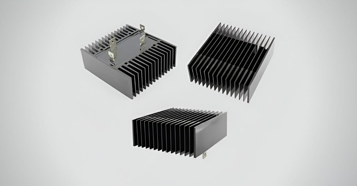
So, let’s break it down to the basics. You’ve got this crucial piece in your vehicle’s electrical system called a regulator/rectifier.
Imagine it as the gatekeeper that transforms your generator’s wild AC (alternating current) into the calm and steady DC (direct current) that your battery needs. This is important because it ensures your battery gets charged just right, avoiding mix-ups with the wrong current type.
Now, inside this handy device, there’s a bunch of diodes. Think of diodes like those one-way streets in your town; they keep the electrical current flowing in the right direction.
This setup keeps your electrical system in check, ensuring your ride runs smoothly and reliably. Pretty cool, right?
How to Test a Rectifier with a Multimeter
Let’s dive into how you can play detective with your vehicle’s electrical system by testing a rectifier with a multimeter. This is one of those skills that can save you time and money, and who doesn’t love that?
Step 1: Understanding Rectifier Diodes
- A rectifier diode is designed to allow electric current to flow in one direction. It has two terminals: an anode and a cathode, with the cathode marked by a white line.
Step 2: Preparing Your Multimeter
- Set your digital multimeter to the diode measurement setting. This mode is for testing diodes, including rectifier diodes.
Step 3: Conduct the Forward Bias Test
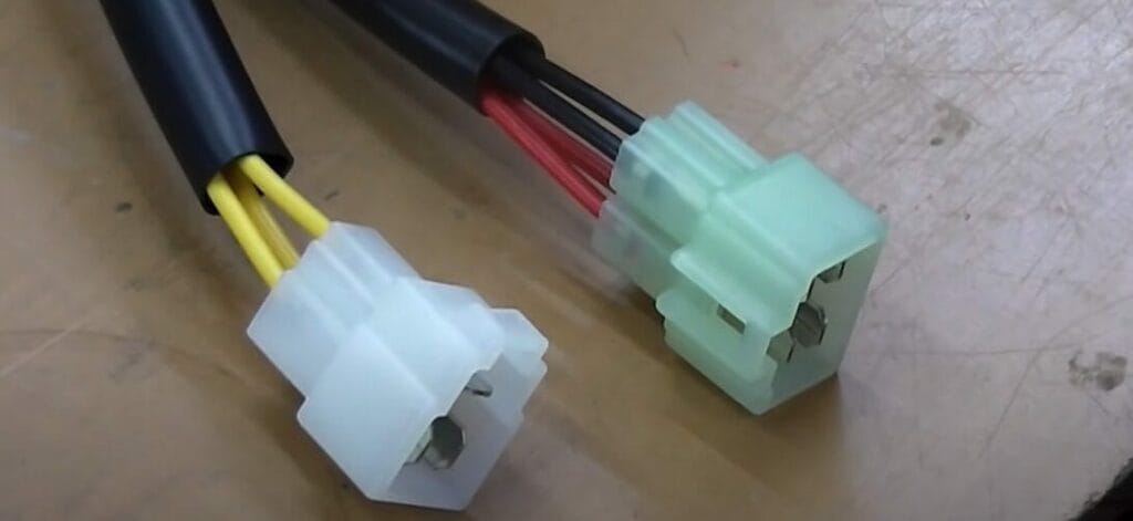
- Connect the multimeter’s red probe to the anode of the rectifier diode.
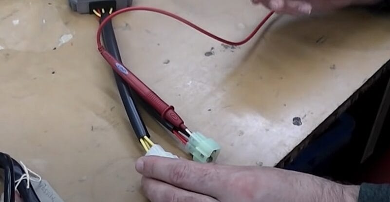
- Connect the black probe to the cathode.
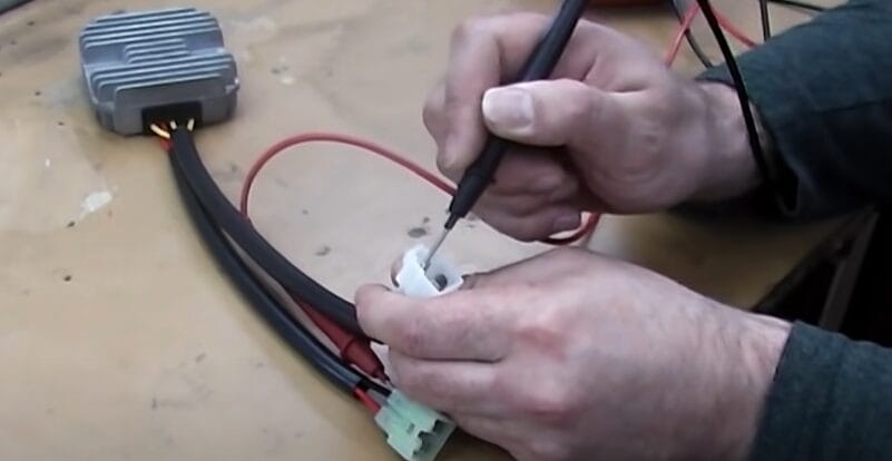
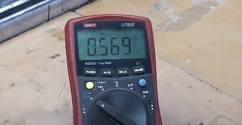
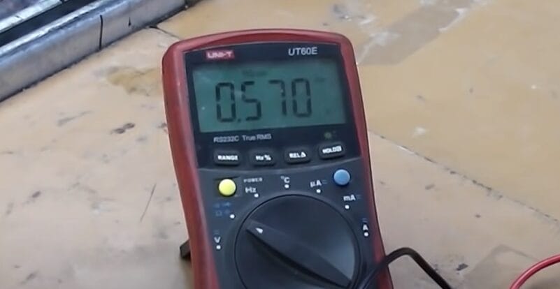
- If the diode functions properly, the multimeter will display a voltage drop between 500 and 600 millivolts. This indicates the diode allows the current to flow in the forward direction.
Step 4: Perform the Reverse Bias Test
- Reverse the connections: place the black probe on the anode and the red probe on the cathode.
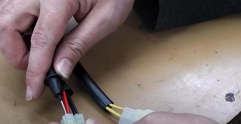

- The diode should not conduct current in this configuration, and the multimeter will not display a voltage drop.
- The absence of a voltage drop indicates the diode correctly blocks current in the reverse direction.
If the diode passes both tests—showing a voltage drop in the forward direction and no voltage drop in the reverse direction—it functions correctly.
RELATED Multimeter Diode Symbol (Guide)
Understanding When to Test the Rectifier: Diagnostic Scenarios
Let’s tackle some common scenarios where a rectifier test isn’t just a good idea—it’s essential.
These real-life situations have shown me the importance of pinpointing the problem before it leads to bigger headaches. Here’s how to spot those moments when your rectifier needs a closer look.
Scenario 1: The Case of the Dying Battery
Imagine you’ve got a vehicle that won’t hold a charge. You’ve tried charging the battery, maybe even replaced it, thinking that was the issue. But lo and behold, a couple of days later, you’re back to square one with a vehicle that refuses to start.
This is a classic sign that your rectifier might be failing. It’s supposed to convert AC to DC and charge that battery, but if it’s on the fritz, your battery won’t get the juice it needs, no matter how new.
Scenario 2: Flickering Lights and Electrical Gremlins
Here’s another scenario: You’re cruising, your headlights start flickering, or your dashboard lights look like a disco.
This inconsistent electrical supply could mean your rectifier isn’t regulating voltage properly. Instead of a steady DC output, it sends out a fluctuating current that makes your vehicle’s electrical components act like they have a mind of their own.
Scenario 3: Overheating Mysteries
Have you ever dealt with a vehicle that overheats, but all the usual suspects, like the cooling system, seem fine? Sometimes, a faulty rectifier can cause excessive heat in itself and throughout the electrical system.
This is because a bad rectifier can lead to overcharging the battery, generating a lot of heat. If you’re scratching your head over an overheating issue, it might be time to check the rectifier.
Why and When to Test
Each scenario points to a deeper issue within the electrical system, where the rectifier could be the culprit. Testing the rectifier becomes crucial when you notice these symptoms because it helps you rule out or confirm the rectifier as the source of your troubles.
Instead of throwing parts at the problem or chasing down dead ends, a quick test can point you in the right direction.
In my experience, getting familiar with these diagnostic scenarios and knowing how to test a rectifier saves time, money, and a lot of frustration.
So next time you encounter one of these electrical mysteries, remember to consider the rectifier—it might just be the key to solving your puzzle.
Troubleshooting Tips for Testing Rectifiers
I’m laying out some troubleshooting tips I’ve picked up. These are the common hiccups you might encounter when testing rectifiers and, more importantly, how to smooth them out.
| Common Problem | What You Might Encounter | How to Resolve It |
|---|---|---|
| Inconsistent Readings | Sometimes, you’ll get readings that don’t make sense, bouncing everywhere. | First, ensure your multimeter is set correctly and has a good battery. I’ve had to double back more times than I care to admit because of a simple oversight like this. |
| No Readings at All | You expect some numbers to appear, but your multimeter is as silent as a ghost town. | Check your connections. It sounds simple, but ensuring that your leads are firmly connected can solve a lot of headaches. I’ve found that a loose connection can make or break your diagnostic efforts. |
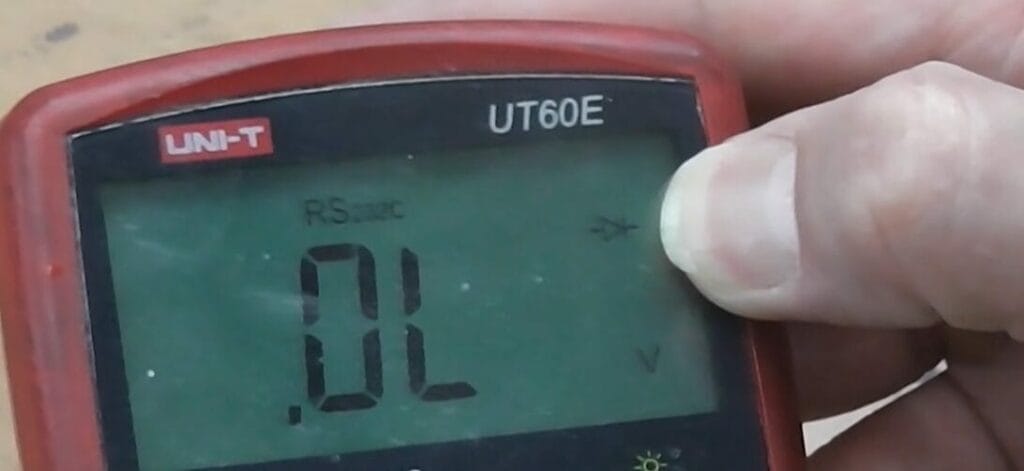
| OL (Open Loop) When You Shouldn’t | Getting an OL reading when you’re expecting voltage? That’s a head-scratcher. | This usually means a break somewhere or the diode is completely shot. Swap out the diode if you can, and trace back your connections. Sometimes, the issue is not with the component but the wiring leading to it. I chased my tail to find a worn wire was the real culprit. |
| Unexpected Voltage Readings | You’re testing for forward bias and finding voltage readings that are off the charts or perhaps too low. | This could be a sign of a diode allowing too much current through or insufficient. Before you swap parts, recalibrate your multimeter. |
Remember, the key to successful troubleshooting is patience and methodical testing. Happy diagnosing!
Frequently Asked Questions
- What Are the Signs of a Faulty Rectifier?
- Keep an eye on signs like your battery not charging up properly, dimming headlights, or trouble getting your vehicle started. These could all point towards a rectifier not doing its job.
- How Often Should Rectifiers Be Tested?
- Make it a habit to check your rectifier as part of your regular maintenance or if something feels off electrically. Staying ahead with these checks can save you from bigger headaches.
- Can a Bad Rectifier Drain the Battery?
- Absolutely. A rogue rectifier can drain your battery, leaving you high and dry when you least expect it. It’s one of those silent battery killers.
- Should I Repair or Replace a Faulty Rectifier?
- Most of the time, rectifiers are sealed deals. Once they’re out of commission, it’s usually time for a replacement. Attempting repairs can be more trouble than it’s worth.
- What Safety Precautions Are Necessary When Testing?
- Before diving into testing, gear up with insulated gloves and goggles. Ensure your engine’s off and the battery’s disconnected to keep things safe. It’s all about taking care of yourself while you take care of your ride.
- Does Weather Affect Rectifier Performance?
- You bet. Rectifiers can get a bit finicky with extreme temperatures. It’s wise to monitor its performance as the seasons change to catch any issues early.
- Single-Phase vs. Three-Phase Rectifiers: Any Testing Difference?
- You have a few more steps when dealing with three-phase rectifiers because of the extra diodes. But the testing principle? It stays the same. It’s all about consistency.
- Can I Test a Rectifier Without Removing It?
- While it might seem convenient, testing a rectifier without taking it out can lead to misleading results because of other circuit components. For a clear picture, removing and testing it solo is best.
- Rectifier Tests OK but Still Having Issues?
- If your rectifier tests okay but still faces electrical issues, widen your search. Look into the stator, battery, and wiring. Sometimes, the issue lies beyond just the rectifier.
References
Organizations:
- The Institute of Electrical and Electronics Engineers (IEEE). https://www.ieee.org/
- Society of Automotive Engineers (SAE) International. https://www.sae.org/
Books:
- “Practical Electronics for Inventors” by Paul Scherz and Simon Monk
- “The Art of Electronics” by Paul Horowitz and Winfield Hill
Website Resources:
- Electronics Tutorials. https://www.electronics-tutorials.ws/
- All About Circuits. https://www.allaboutcircuits.com/
- CircuitBread. https://www.circuitbread.com/
- Electrex World Ltd. https://www.electrexworld.co.uk/
Video References:
Electrex World Ltd