15 min read
How to Wire a Double Switch (6 Steps)
This article will guide you step-by-step to wire a double switch.
Double switches are convenient for controlling two appliances from a single spot, two circuits, whether two halves of the same or two separate ones or the same one from two different locations.
Wiring for either case is not difficult if you follow the instructions carefully. However, I will focus on the first type (single housing, 2-gang, 1-way) because it’s commonly understood as a “double switch.”
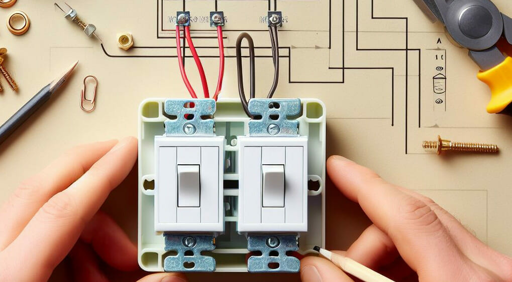
To wire a double (2-gang, 1-way) switch, connect the feed wire to the side with a connecting tab marked COM, the load wires to the terminals on the other side without a connecting tab marked L1 and L2, and the ground wire to the ground terminal.
I’ve included illustrations and wiring diagrams to make it easy, so keep reading.
Double Switches
2-Gang 1-Way Switches
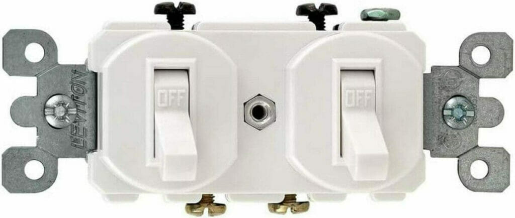
A double switch typically has two levers or toggles in a single housing.
This type is a combination double switch, which contains two separate switches in a single housing that can be used to control either a single or two separate circuits from a single location:
- To control two halves of the same circuit (single-circuit installation);
- To control two separate circuits (separate-circuit installation).
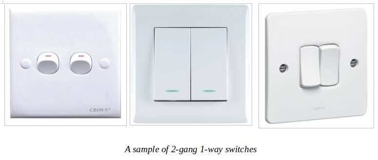
Technically, this is a single 2-gang 1-way switch, performing the function of 2 single-pole (SPST) switches in a single unit. You might also see them described as dual/double rocker witches, a duplex toggle, or a combination double switch. Below is a sample of 3 different designs (in addition to the one at the top).
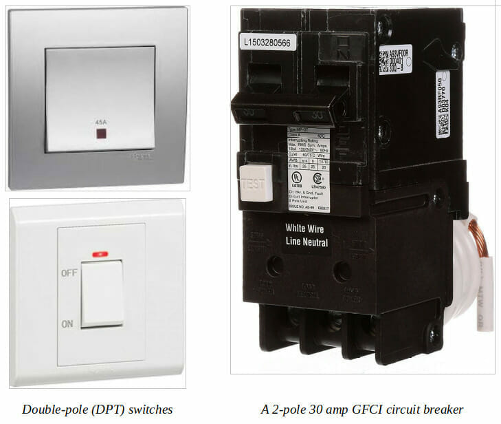
Double-Pole and 3-way switches
A double switch can also refer (less commonly) to a 1-gang, double-pole switch and a pair of 1- or 2-gang, 3-way switches.
A double-pole switch looks like a single (regular 1-gang) switch externally. Still, the two levers are connected internally, allowing you to control both simultaneously with a single flip on or off. For example, you can control two light fixtures simultaneously, a light and fan, or any two circuits. It’s also possible to control two halves of the same circuit simultaneously.
A 3-way switching system comprises two separate switch housings in two different locations connected together so that you can operate a single (or more) appliance from either one. A common use is on the top and bottom of a staircase.
I will focus on the 2-gang, 1-way type of double switch and briefly cover the two other types.
Wiring a Double Switch (Single Housing, 2-Gang)
This section covers double switches in single housings that are not interconnected but separate.
They allow you to operate two lights or appliances from the same location.
Wiring a double switch involves feeding through and connecting the wires to each of the two switches separately.
Requirements
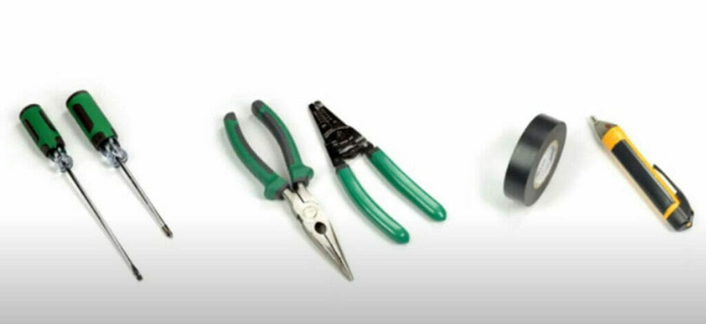
You usually need the following items to wire a combination double switch:
Screwdriver, nose pliers, wire stripper, electrical tape, voltage detector.
Safety
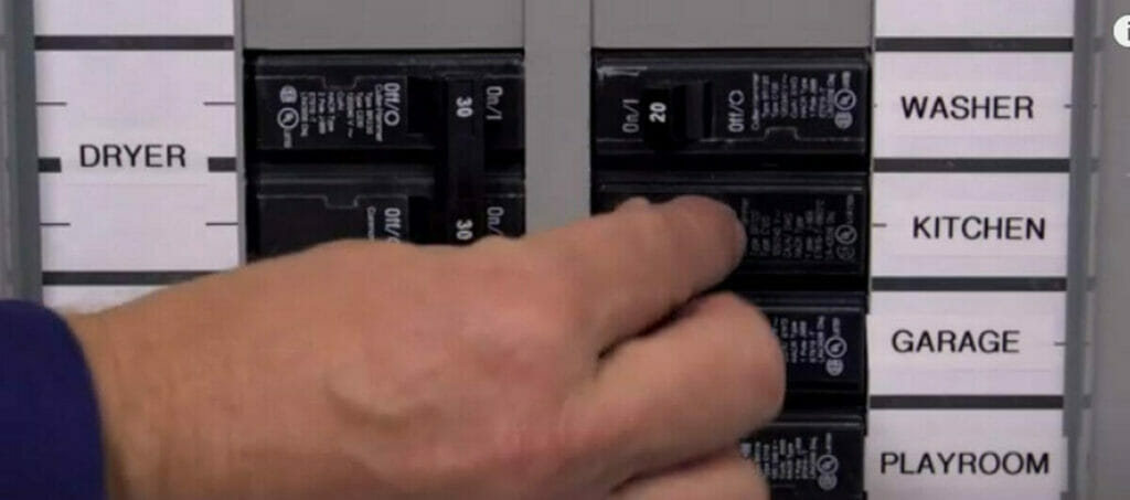
Regardless of the type of double switch, the first thing to do before touching an electrical system is to switch the power supply off.
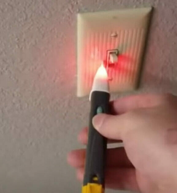
Go to the main panel in your home and switch the circuit breaker off for the circuit you will be working on. For additional safety, you should also wear gloves and rubber-soled shoes. Use a voltage detector or electrical tester to confirm there is no power in the circuit.
Also, only hot wires enter a switch, usually all black or black and red. The neutral wire should never be wired to any switch. The white wire, normally used for neutral, is only connected to a switch if reidentified as a hot wire.

As with any other switch, only the hot (live) wires should connect to it, which are the line (from the power source) and load ones (from the appliances), plus the ground wire to its housing. NEVER connect the neutral wire to it. Doing so will create a short circuit and burn the wiring. Only connect the neutral wire to the power source and the loads.
Before Wiring
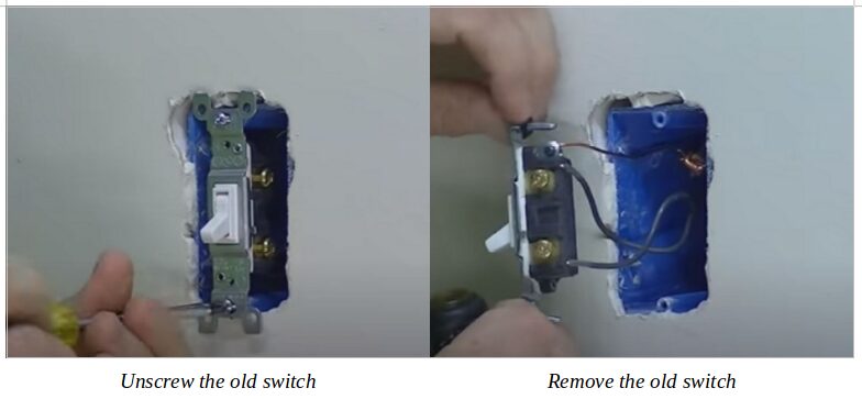
Remove the existing switches if applicable.
Remove the cover screws, then remove the terminal screws and completely remove the switch, leaving the box intact. Note the wire, i.e., the feed or line wire and the load wires from the two appliances.
If there is no existing switch, you may need to install a switch box if one is not present already and feed the wires through it for wiring to the double switch.
Wiring a Double Switch for a Single Circuit
This method wires a combination (2-gang, 1-way) double switch to a single circuit with 2 separate connections (or two halves).
You only need to connect three wires to a single circuit to wire a double switch.
One FEED wire supplies power to both halves of the switch, while the other two POWER wires carry power to the individual appliances.
The feed wire is so-called because it always lives with electricity. It brings power into the switch, which then connects to the appliance according to its position. Hot wires are normally black, red, or white and reidentified as hot.
Follow this procedure for single-circuit wiring of separate double switches:
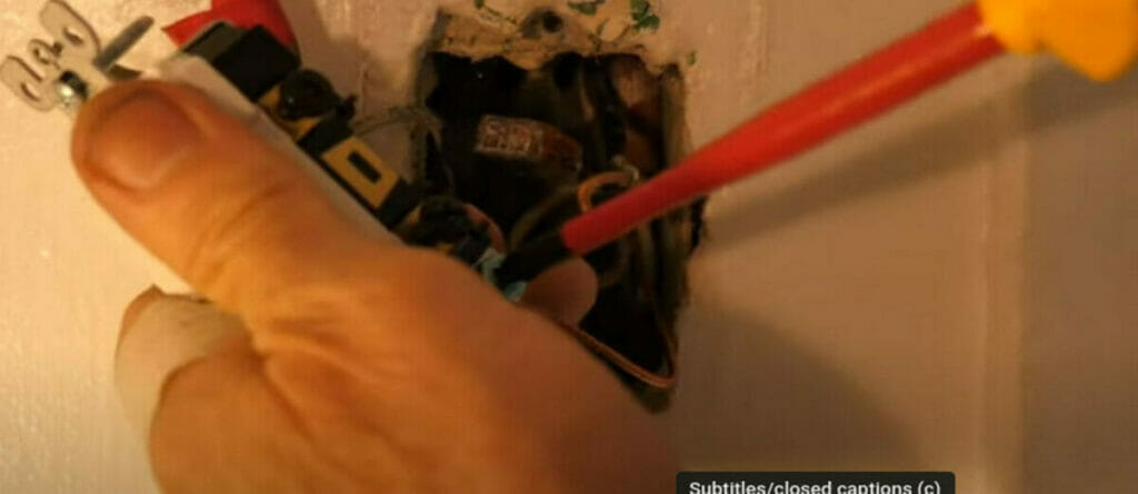
Step 1: Connect the Feed Wire
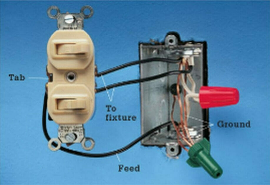
Connect the black feed (or line) wire to the side of the switch with a connecting tab or fin, which might be marked C or COM.
If you’re unsure which one is the feed wire, ensure no conductor is touching any metallic part and temporarily turn the power on. Use a tester to see which one has power. That will be the feed wire. Be extremely careful when doing this. Only touch the conductors with the tester.
Remember to turn the power off again before continuing.
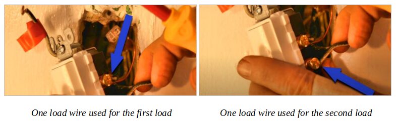
Step 2: Connect the Load Wires
Connect the two power-carrying (or load) wires to the side of the switch that does not have a connecting tab and the other ends to the appliances or lighting fixtures.
The load terminal might be marked L1 and L2.
The load wires may also be black, but one or both may be white, reidentified as a hot wire.
Step 3: Terminate the Neutral Wires
Connect the neutral (white) wires together with a wire connector or terminal block to terminate them. They must not connect to any of the switch terminals.
Step 4: Ground the Switch
The ground wire, usually green, yellow, or bare copper, attaches to the green screw on the switch. It helps to protect the switch from an electrical short circuit.
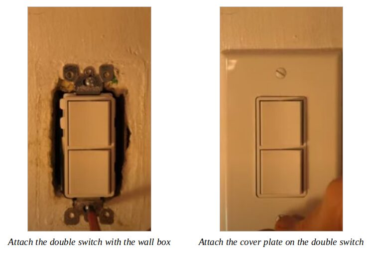
Step 5: Attach the Switch
Securely attach the switch to the switch box after completing the wiring. Leave both switches in the off position.
Step 6: Check the Switch
Then, turn the power on to check the combination double switch.
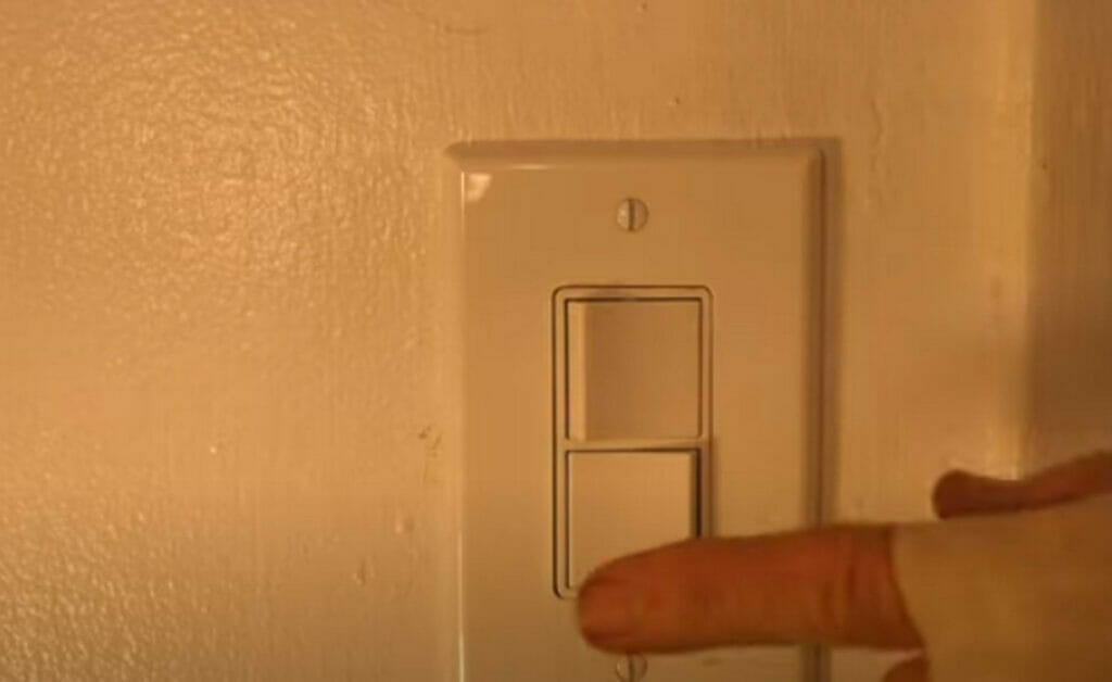
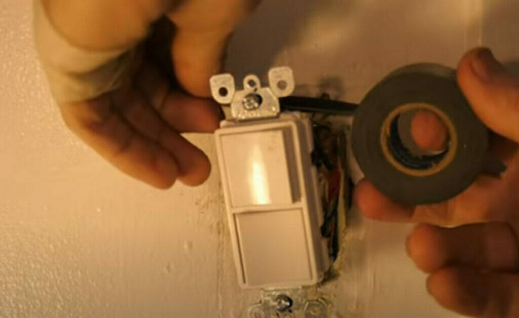
Test the switch before attaching the cover and wrap electrical tape around all the terminals once confirmed.
Wiring a Double Switch for Separate Circuits
This method uses a combination (2-gang, 1-way) double switch to two circuits.
You connect four wires to wire a double switch to two separate circuits.
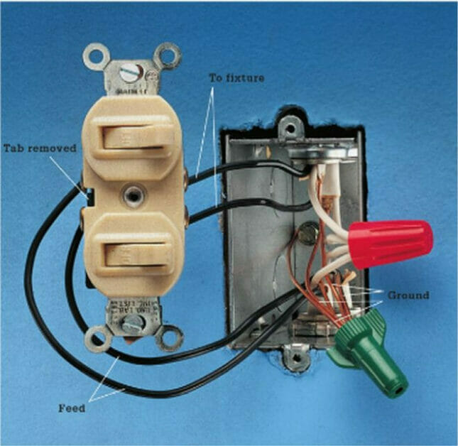
After removing the metal connecting tab joining two of the screw terminals, connect the 4 wires to the switch. Follow this procedure for separate-circuit wiring of separate double switches:
- Step 1: Connect the two feed wires to the side of the switch with a connecting tab.
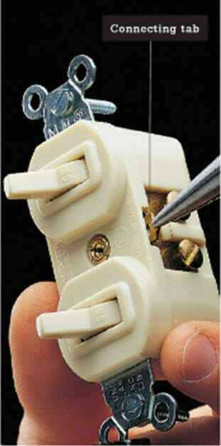
- Step 2: Remove the connecting tab using a screwdriver or needlenose pliers.
- Step 3: Connect the two power-carrying wires to the side of the switch that did not have a connecting tab and the other ends to the appliances or lighting fixtures.
- Step 4: Connect the neutral (white) wires together with a wire connector to terminate them.
The procedure is very similar to wiring a single circuit, except for the extra feed wire and the need to remove the connector from one side.
Practical Applications
A combination (2-gang, 1-way) double switch has many practical applications.
It absolves the need for two separate SPST switches side by side, saving you space. Here are a few examples of pairs of appliances often connected to a double switch:
- A light and a ceiling fan in a living room
- A ceiling fan with a built-in light
- Two lights in a room
- A light and an extractor fan in the bathroom
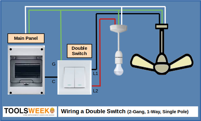
It doesn’t matter what pair of appliances (loads) you connect to a double switch as long as the total amperage doesn’t exceed its rating. The wiring in all cases will be the same:
- The black line wire from the panel goes to the C or COM terminal (side with a connecting tab).
- The black/red load wires from the loads connect to the load terminals (L1 and L2, on the side without a connecting tab).
- If it has one, the ground wire connects to the two loads and the double switch on the G or GROUND terminal.
Wiring a Double-Pole Switch
A double-pole or two-pole switch simultaneously controls two separate electrical circuits with a single flip.
It functions as two conjoined switches to ensure the power is delivered or turned off to both circuits. You can use double-pole switches with various appliances. It is commonly used for high-powered ones that must operate and be switched together, typically on 30-amp circuits protected by a double-pole 30-amp circuit breaker.
Double-pole switches can be DPST (double-pole single-throw) or DPDT (double-pole double-throw).
Wiring Diagram
Here’s a sample wiring diagram to help wire a double-pole switch:
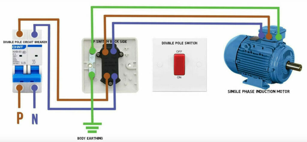
The above double-pole switch is connected to a single appliance (an induction motor), which requires it because both hot wires provide 240 volts and must switch on or off together.
Procedure
To wire a double-pole switch, we connect the hot and ground wires (never the neutral one) as follows:
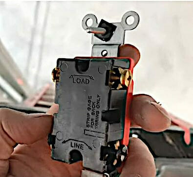
- Step 1: Connect the black line wire to the line terminal on one side of the switch and the black load wire above it on the load row.
- Step 2: If it’s a 3-conductor cable, connect the red (second hot) line wire to the line terminal on the other side and the corresponding load wire above it. If it’s a 2-conductor cable containing a white wire, reidentify it as the second hot wire.
- Step 3: Splice the green wires together and connect them to the green screw terminal.
Wiring a 3-Way Switch
A 3-way switching arrangement involves two switches in two locations controlling the same load, such as a light on a stairway.
Procedure
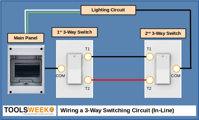
As there are two switches, i.e., in separate housings positioned at a distance, we shall call the one near the panel the primary switch and the other the secondary switch.
Follow these steps (for an inline configuration):
- Step 1: Connect the hot wire from the power source to the primary switch’s common (C or COM) terminal.
- Step 2: Connect the secondary switch’s common terminal to the load.
- Step 3: Connect the two corresponding traveler terminals (T1 and T2) to each other, preferably using black and red wire to distinguish them.
Your wiring should look something like this:
References
Website Resources:
- 2-gang 1-way switches
- https://sqgroup.com/product/2-gang-1-way-switch/
- https://www.velocitydiy.com/showproducts/productid/2950280/13a-2-gang-1-way-switch/
- https://www.legrand.com/ecatalogue/730024-single-pole-switch-synergy-2.html
- Double-pole switch (45A). https://uae.sharafdg.com/product/schneider-electric-kb31dr45n_as-vivace-silver-45a-250v-double-pole-switch-with-neon-cooker-control-water-heater/
Books:
- B&D. The Black & Decker complete guide to wiring. Creative Publishing International, Editors of Creative Publishing. Cool Springs Press. 2008
Video References:
Daily Electrician
Leviton
Everything Home TV
Learning Engineering
Sparky Channel