9 min read
How to Check Continuity with a Multimeter (2 Methods)
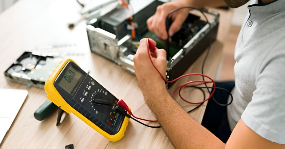
In my years tinkering with all sorts of electrical projects, I’ve found one tool to be a game changer: the multimeter. It’s a real powerhouse, especially for continuity testing.
Quick Summary: Here’s a quick run-down to continuity testing for these two methods:
🔧 Setting Up: Flip the multimeter to the respective mode – that sound wave icon.
🔌 Connecting Probes: Black probe in COM, red in VΩmA.
🔍 Testing: Attach each probe to the circuit ends.
In this article, we’ll dive deep into two reliable methods for continuity testing. I’ll also sprinkle in some handy maintenance tips and point out common mistakes to steer clear of. Let’s get our hands dirty and explore the world of continuity testing with multimeters!
Methods to Check Continuity with a Multimeter
Checking continuity with a multimeter can be done using several methods, depending on the features of your multimeter.
Method #1 – Continuity Mode
Here are the detailed steps for continuity testing using the multimeter in Continuity Mode:
Step 1: Setting the Multimeter
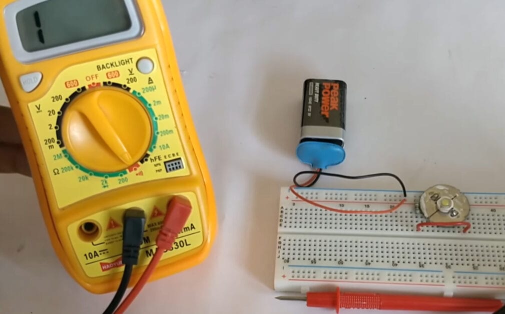
I start by setting my multimeter to the continuity symbol, like tuning an instrument.
Step 2: Getting Probes in Place
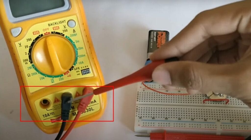
I plug the black probe into the COM port and the red into the VΩmA port. It’s crucial to ensure the probes are correctly placed for accurate testing.
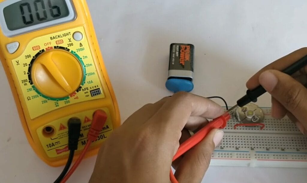
Step 3: Testing the Continuity
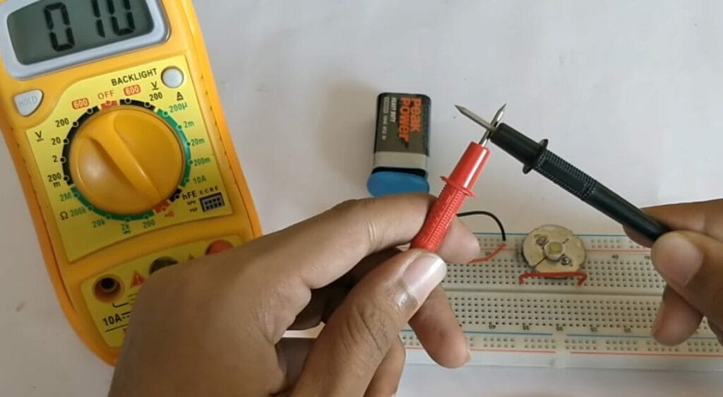
Touching the probes to the terminals, I look for a beep or OL reading. No beep and an OL reading indicate a break in the circuit.
Step 4: Using a Conductor for Testing
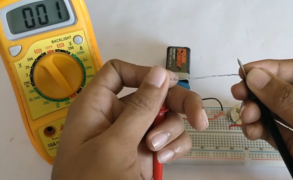
I use a conductor, like a filament, to test both ends with the probes. When I hear a beep and see a zero reading, it signals continuity.
Step 5: Circuit Check for Troubleshooting
I remember once troubleshooting an LED circuit. Methodically checking each connection, I finally found the faulty spot. It’s almost like detective work, using each beep as a clue.
Method #2 – Resistance Mode (Ohmmeter)
Another handy technique I use for continuity checking is the resistance mode on the multimeter, known as the ohmmeter.
This method is a fantastic alternative when you don’t have a dedicated continuity mode on your multimeter.
Step 1: Set the Multimeter
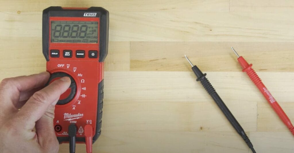
I start by setting the multimeter to the Ohms or resistance with a tone setting. It’s crucial for getting those precise readings.
Step 2: Disconnect Power and Isolate the Component
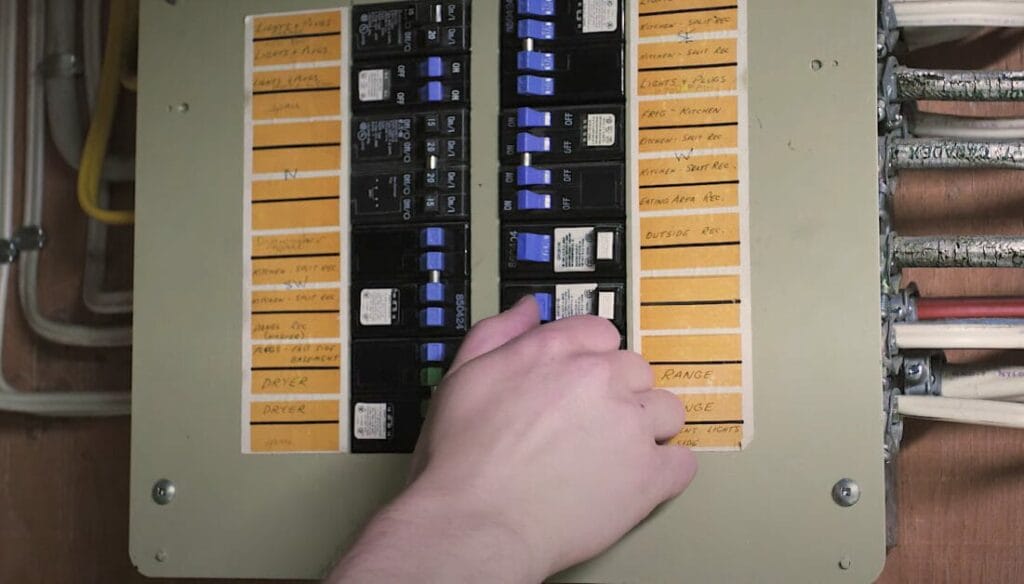
Safety first! I always disconnect the power via the main power supply.
And I isolate the component that I’m testing.
Step 3: Check for Continuity
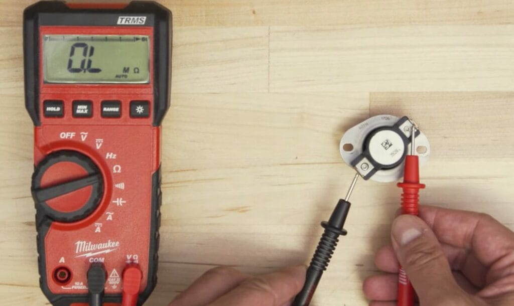
I touch each probe to the component’s terminals. If the multimeter reads OL or Open Loop, it’s a sign there’s no continuity.
Step 4: Evaluate Resistance
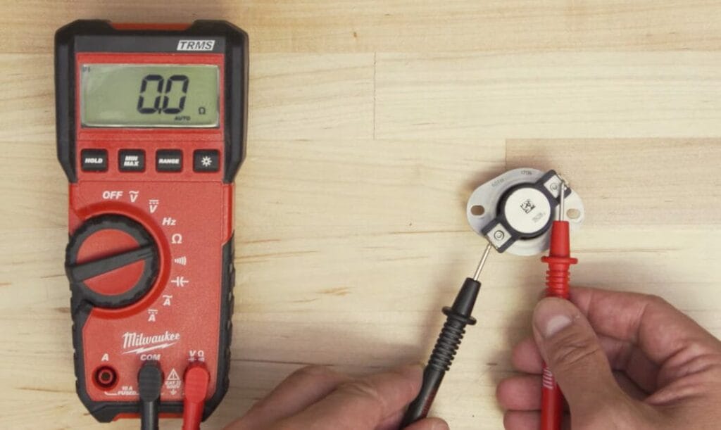
If there’s continuity, the multimeter shows a reading above 0 ohms. It’s fascinating to see the difference in resistance between non-load components like switches and load components like motors.
There you have it, continuity checking with a multimeter – a surefire way to keep your circuits in check!
Troubleshooting Tips for Continuity Testing
Alright, here’s a little something I’ve put together for you. In my time working with multimeters, I’ve come across a few snags here and there during continuity testing.
Think of it as your troubleshooting cheat sheet crafted from my experiences in the field! Let’s dive in and get those tests running smoothly.
| Issue | Possible Cause | Solution |
|---|---|---|
| No Beep Sound | Poor probe contact or broken wire | Ensure the probes are firmly connected and check for wire breaks. |
| Inconsistent Readings | Loose connections or corroded terminals | Tighten connections and clean terminals for better contact. |
| Multimeter Displays OL | Open circuit or break in the continuity | Inspect the circuit for breaks or disconnects and repair if needed. |
| False Positives | Proximity to other conductors or wires | Isolate the wire or circuit you’re testing from others to avoid interference. |
| Continuous Beeping | Short circuit in the system | Check for unintended connections that might cause a short circuit. |
Remember, continuity testing is straightforward but requires attention to detail. Ensure your multimeter is in good working order, and always double-check your connections for accurate results.
Advanced Continuity Testing: Tips and Common Pitfalls for Pros
Alright, let me share with you some advanced multimeter tricks I’ve picked up along the way:
- Avoiding False Negatives: I learned that corrosion or dirt can lead to misleading readings. I make sure my test points are spotless for the most accurate results.
- Capacitors and Their Charge: Working with circuits that have capacitors? Remember, these components store charge. I always safely discharge them before testing to avoid any skewed data.
- Lead Integrity Checks: I routinely check my multimeter leads for hidden damage. Broken or worn leads can mess up your readings.
- Temperature’s Effect on Resistance: Temperature can play tricks on your resistance readings. If things seem off, I consider the ambient temperature as a factor.
- Regular Calibration: Like any precision tool, I keep my multimeter calibrated. Accuracy can drift over time, and regular calibration keeps it in check.
There, you have a few advanced tips to hone your multimeter skills. Stay sharp and happy testing!
Staying Safe While Testing: Multimeter Safety Protocols
Discuss safety when using a multimeter – it’s as crucial as the tool. Whether you’re in a home workshop or on a commercial site, following these safety protocols can make a world of difference:
- Always Disconnect Power: Before you start, ensure the system you’re testing is powered down. It’s a fundamental rule to prevent shocks.
- Wear Protective Gear: In certain environments, like industrial settings, wear safety glasses and insulated gloves.
- Use the Right Settings: Select the appropriate function on your multimeter for the job. Misconfigured settings can lead to inaccurate readings or even damage to the multimeter.
- Check Your Equipment: Regularly inspect your multimeter and probes for any damage. A small crack or wear can lead to big problems.
- Be Mindful of Your Surroundings: Especially in more complex environments, be aware of potential hazards like exposed wires, wet areas, or flammable materials.
Remember, the key to effective testing is not just skill but also ensuring your safety and the safety of those around you. Stay alert and stay safe!
Frequently Asked Questions
- Can Continuity Testing Damage Sensitive Components?
- No, continuity testing is low-voltage and typically doesn’t damage components. However, always handle sensitive components with care.
- Can I Use Any Multimeter for Continuity Testing?
- Most multimeters have this function, but if yours doesn’t, use the resistance mode instead.
- Do Temperature and Humidity Affect Continuity Tests?
- Yes, extreme temperatures and humidity can affect readings. Always consider your environment when testing.
- What If My Multimeter Shows a Reading But Doesn’t Beep in Continuity Mode?
- This could mean there’s partial continuity. Check for any resistive elements in the circuit that may affect the reading.
- Is It Possible to Test Continuity on Wires with Insulation?
- Not directly. You’ll need to access the bare wire ends or use piercing probes for accurate testing.
- Why Does My Multimeter Show Continuity Everywhere on a Circuit Board?
- This might indicate a short circuit, or you might be testing a common ground point. Double-check the test points.
- Is It Necessary to Remove a Component from a Circuit Board for Continuity Testing?
- It’s advisable, especially for accurate readings, as other circuit elements can interfere.
References
Organizations:
- Occupational Safety & Health Administration (OSHA). https://www.osha.gov/
- American National Standards Institute (ANSI). https://ansi.org/
Books:
- “Practical Electronics for Inventors” by Paul Scherz and Simon Monk. http://instrumentacion.qi.fcen.uba.ar/libro/Scherz.pdf
- “The Art of Electronics” by Paul Horowitz and Winfield Hill. https://artofelectronics.net/
Website Resources:
- All About Circuits. http://allaboutcircuits.com/
- Electronics Hub. http://electronicshub.org/
Video References:
Circuit Digest
AMRE Supply