10 min read
How to Check Continuity in a Long Wire (4 Steps)
This article shows how to check the continuity in a long wire so that you can verify if it has a continuous electrical path.
A multimeter can check the continuity of various wires and other conductors. A continuity test helps identify a fault in a circuit or device by indicating whether the wire is normal, broken, or weak. But the dilemma is how to use the multimeter if the wire is too long for its probes, such as when its ends are at opposite ends of a room or in different parts of the house.
To check the continuity in a long wire:
- Set the multimeter to an ohms range (200 ohms is recommended).
- Plug the red (positive) probe into the socket labeled V and the black (negative) probe into the COM socket.
- Ping the probes together to check for continuity between the multimeter’s probes.
- Switch the power off and disconnect any appliances.
- Attach another long wire to one end of the main wire to bring it closer to the multimeter.
- Attach one probe to the close end of the long wire being tested and the other probe to the end of the attached wire.
- Interpret the reading: close to zero means the wire is continuous if it’s close to zero but not if it’s very high or remains at OL.
I will cover more details below.
Requirements
Use a wire stripper if the wires need stripping.
To conduct a continuity test, we will use a multimeter. You could also use an ohmeter, which is dedicated to checking only resistance.
A digital multimeter is the ideal type of multimeter to use. Instead of a needle pointer for readings, it has a display unit showing the reading. However, if you cannot get a digital multimeter, an analog one will do.
Checking Continuity in a Wire
Before checking continuity in a long wire, let’s understand what continuity is and how to check continuity in normal situations when a wire is short.
We will then adapt the procedure for long wires. Follow the detailed steps below to check if a wire has a continuous electrical path or not.
What is Continuity in a Wire?
In electrical engineering, continuity describes an uninterrupted flow of electrical current in a conductor, such as a wire.
Sometimes, wires develop faults that render them non-conductive or partially conductive. A lack of continuity in such wires stops the smooth flow of current from a power source or outlet to the connected electrical appliance. The wire must be replaced if discontinuity is confirmed.
So, it is imperative to know how to check the continuity of a wire to be sure.
Resistivity
Electrons collide with the conductor’s ions while flowing through a wire.
The collision produces resistance to the flow of electrical current. So, an electrical wire conducts electricity, but it also functions technically as a resistor by controlling or restricting current flow.
It will be necessary to know the color codes of electrical wires and understand that the resistivity of wires varies according to length, thickness, and type.
Resistance in Long Wires
Coinciding electrons and conductor ions in longer wires is more frequent than in shorter ones.
The collision frequency of electrons and ions in a wire varies linearly with resistance. So, resistance in long wires is high. Expect higher resistance readings in long wires.
Setting the Multimeter
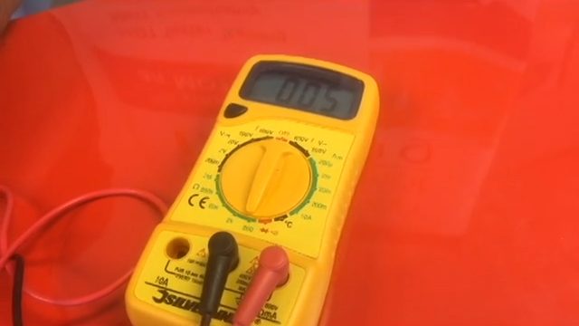
When checking for continuity, set the Multimeter to Continuity Test Mode.
If you don’t see such an option, are unsure what it means, or have an analog multimeter, set the knob to the ohms position to measure resistance.
Assemble and set your multimeter properly before testing continuity to get plausible results.
The Display Unit
After setting the multimeter, ensure the display unit reads OL. It stands for “Open Loop,” the highest resistance measurement, except for faulty wires.
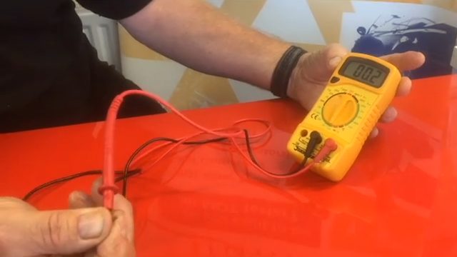
Probe Leads
The multimeter has two probe leads: a negative black lead and a positive red lead.
Insert the negative probe lead into the port or socket labeled COM (common), and the positive probe lead into the socket labeled V (Ohms). A newer multimeter may have a contact point instead of a COM port.
Verify that both leads are plugged into their respective sockets properly. You may ping them together, as shown below, which should give a small reading.
Safety
Safety is paramount.
If testing an electrical wire in use, disconnect it from its power source before conducting a continuity test to avoid working with live wires, especially if you are a beginner. Switch off and unplug any connected motorized appliance.
Also, disconnect other electrical devices like laptops & desktops, TVs, and air conditioners. This way, you will ensure their safety in the event of an electrical fault triggered by the continuity test.
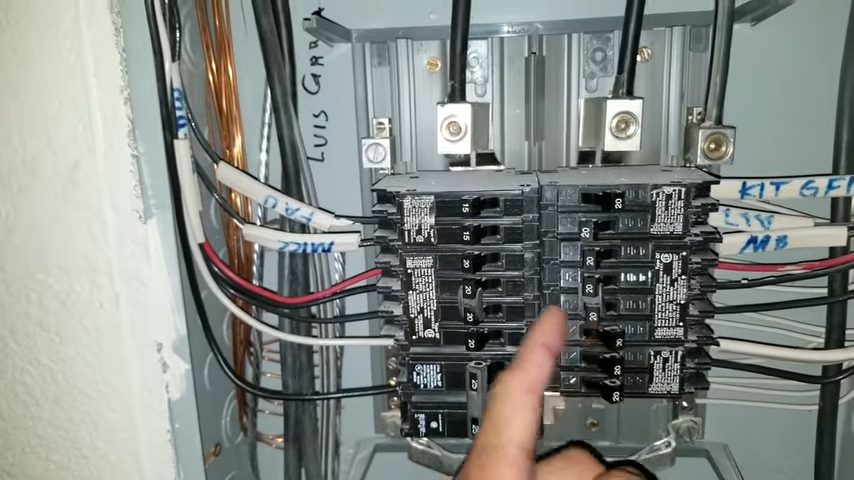
You turn off the power supply to the wires you are working on at the breaker panel. If you are unsure which breaker unit to flip off, turn off the main power supply to the entire household or facility.
If you have a circuit box in the house, turn off the power by pulling the main disconnect or removing the fuse block. Turn off a particular circuit as follows:
- Unscrew an individual fuse.
- Avoid joining the circuit or wires and other connections.
Conducting a Continuity Test
Ensure you’ve done all the preliminary steps before conducting a continuity test, which I described above:
- Set the multimeter to Continuity Test Mode (to measure resistance in ohms).
- Check the display – It should read “OL”.
- Connect the probe leads to the multimeter – Insert the negative probe’s lead into the COM port and the positive probe’s lead into the socket labeled V (Ohms).
- Make sure the power supply is off.
- Strip the wire ends – Strip off the insulation from both ends of the wire to about 1/2-inch depth if they’re not stripped already.
Now, you can begin the test.
Step 1: Attach the Probes
Touch the probe leads on the two ends of the wire.
The wire doesn’t have polarity, so the placement order is no issue. You can attach either probe to either end.
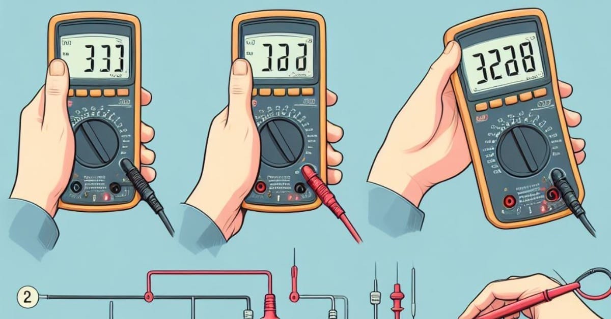
Step 2: Analyze the Reading
Check the multimeter’s display unit for the readings and interpret it as follows:
| Multimeter Reading | Interpretation |
| OL | Open Loop – The initial display to look for when the resistance is infinite or overloaded because you probably haven’t attached the probes yet. |
| A low reading (close to zero) | Low resistance means high current flow, indicating the wire is good can capable of doing what it is designed for. Confirm by selecting a different resistance range. If it’s very low, ensure there is no short in the circuit, the wire has the right gauge, and the circuit has the right-sized breaker. |
| Unity (value of 1) | Change the resistance range to recheck. |
| A high reading (close to the setting’s upper limit) | High resistance means low current flow, indicating the wire is poor at allowing current to flow. It might be due to a weak point in the wire. If it’s very high, consider replacing the wire. Replace it if it’s infinite because there’s a break someone along the wire. |
A low value means current continuity between the probe leads, i.e., good current flow. It confirms a continuous electrical path in the wire, so the circuit is complete.
If the multimeter remains on OL instead, there is no continuity in the wire. The continuous electrical path may be broken. Such wires cannot transmit electrical current and must be replaced.
Hearing a Beep
If your multimeter has a sound feature, don’t ignore the beeps when checking continuity.
Listen to the multimeter closely because a beep usually signifies continuity (the absence of resistance in the wire being tested), which means the wire has a continuous electrical path.
For a dead circuit, take out the wires and insert both probe leads into the multimeter jacks. That way, the probe leads won’t be attached to each end.
Checking Continuity in a Long Wire
Now, we will adapt the above procedure for checking continuity in long wires. Follow the detailed steps below to check if a long wire has a continuous electrical path or not.
Step 1: The Ohms Range
A 200 ohm range is the recommended ohm setting for long wires.
The ohms range is vital in determining resistance. We normally use low ohm setting values for short wires.
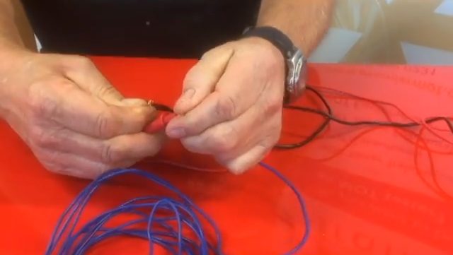
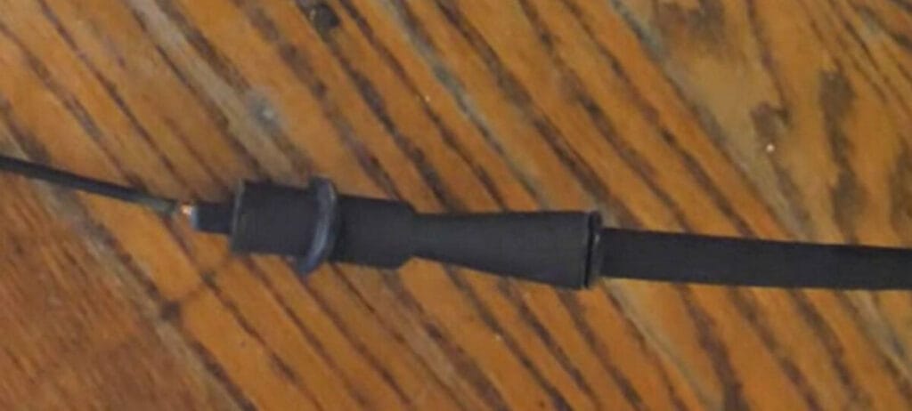
Step 2: Attach a Wire
The way to check the continuity in a long wire is to attach a wire, preferably of the same gauge, to one end of the tested wire to bring it closer and allow for the use of the multimeter.
The attached wire must have known good continuity, which you should retest before attaching to the main wire.
Step 3: Attach the Probes
Attach the multimeter’s probes as follows:
- Attach one probe to one end of the main wire (to which you are close).
- Attach the other probe to the end of the attached wire connected at the other to the farthest end of the main wire being tested.
Step 4: Interpret the Reading
With the probes attached, you are now ready to see and interpret the reading on the multimeter.
See the earlier Step 2 (under Conducting a Continuity Test) to interpret it.
References
Video References:
Premier Mot Training
Sparky Channel