7 min read
How to Wire the Exciter Wire on an Alternator (1,2 & 3 Wire Methods)
This article will show you how to wire the exciter wire on an alternator.
The exciter wire, which turns the voltage regulator on and is essential for starting your car, is required to generate the required voltage for the alternator to function. It connects the voltage regulator’s field terminal (usually blue) to the alternator’s L terminal.
The methods used to wire the exciter wire on an alternator differ by type – whether it is a one-wire, two-wire, or three-wire alternator.
- The one-wire type is self-exciting. It can be excited using a DC motor and a mobile charger.
- The two-wire alternator has three main connections, and the three-wire alternator has three main connections.
Besides the connector to the voltage regulator, they have terminals for wiring the battery, grounding, and sensing the voltage level.
The wiring connections are detailed.
What the Exciter Wire Does
The exciter wire generates the required voltage for the alternator to function and, thus, for the car to start.
However, the exciter wire is not required in modern vehicles with built-in voltage regulators. It is only found in vehicles with alternators and external voltage regulators.
What is an Exciter Wire?
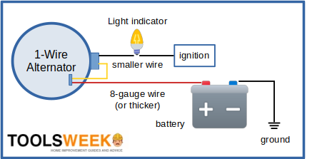
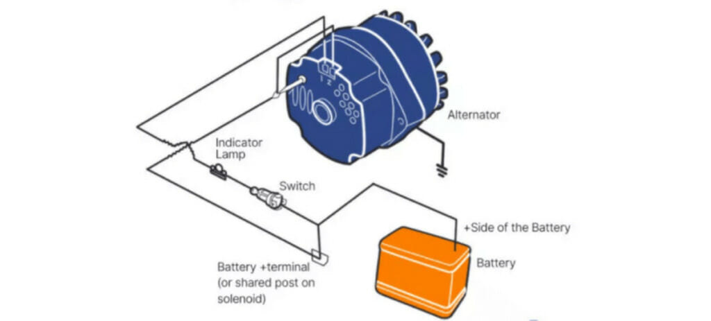
The exciter wire is a small strand connected to a switch on the alternator triggered by the ignition switch. Normally, it is connected to the indicator light that shows the battery charge.
At the alternator end, it is connected to the ‘L’ terminal so that when you start the ignition, it powers on the alternator to start producing electricity to power, in turn, other electrical components in the vehicle.
Requirements for Wiring the Exciter Wire
Below is a list of things you will need and be working on to wire the exciter wire on an alternator.
Things You Will Need
You will need the following things:
- Vice
- Crocodile clips
- 12-volt headlamp bulb
- Multimeter
- Mobile charger
- Wooden board (approx. 30 x 30 cm)
Things You Will Be Working on
You will be working on the following components in your car:
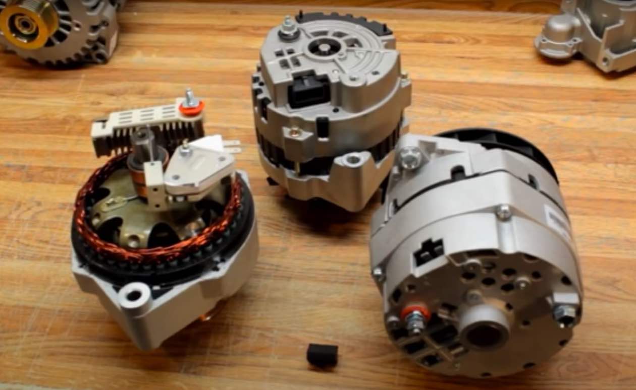
- The alternator
- Pulley and belt
- A 500W DC motor
Other Things to Do
In addition, you will need to take care of the following things:
- Disconnect the car’s battery before doing mechanical work like you will be doing here.
- Do all the mechanical tasks (disconnections and connections) before working on the electrical tasks.
Exciting the Exciter Wire (One-Wire Alternator)
A one-wire alternator is self-exciting. It can spark itself.
I’ve divided the procedure to excite the exciter wire into six steps.
Step 1: Mount the Motor
Connect a pulley to a 500W DC motor shaft and mount the motor on one side of the wooden board.
Step 2: Set the Vice
Set the vice on the other side of the board. You can use screws to mount it and the alternator, too.
Step 3: Connect the DC Motor
Connect the DC motor and alternator using the pulley.
Step 4: Electrical Connections
Connect the brushes of the positive red cable to the alternator’s positive terminal. Then, connect the negative terminal of the brush (it may be blue or black) from the rotor field to any part of the alternator’s casing (as the ground).
Step 5: Attach the Mobile Charger
Using a 5-volt mobile phone charger, attach its positive wire to the alternator’s positive terminal and its negative wire to the alternator’s casing (as the ground).
Step 6: Rotate the Alternator’s Shaft
Using the DC motor as the rotating source, rotate the alternator’s shaft. Disconnect the charger once the motion starts.
You will have excited the alternator by following all the six steps above.
Wiring the Exciter Wire (Two/Three-Wire Alternators)
The method for wiring the exciter wire differs a little depending on whether you have a 2-way (3 connections) or 3-way (4 connections) alternator.
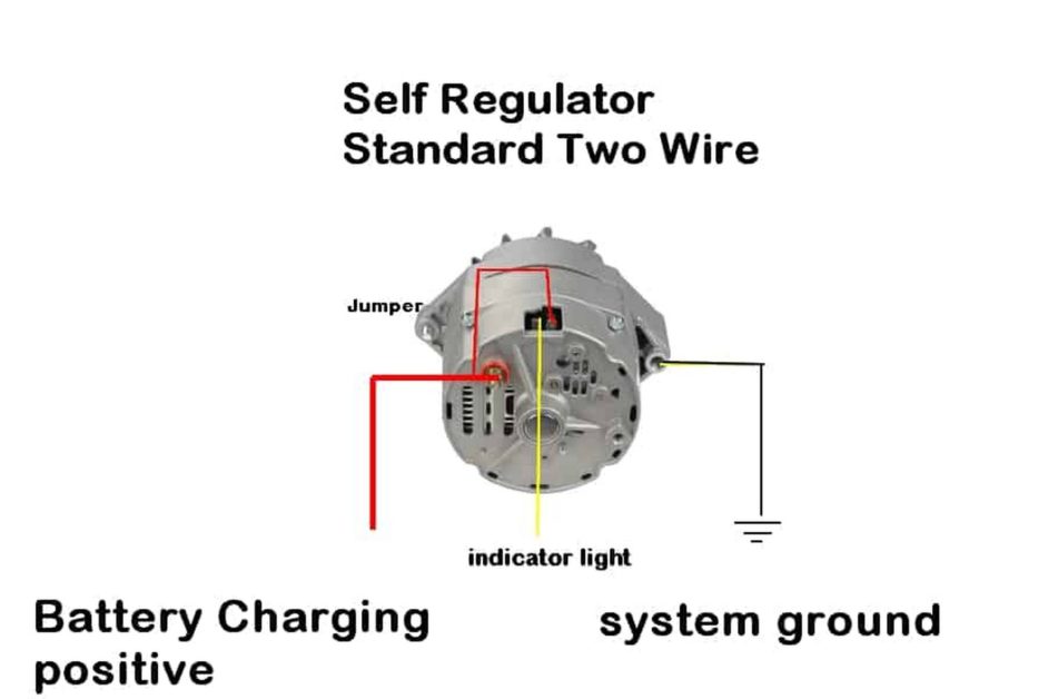
Two-Wire Alternators
A 2-way alternator has three electrical connections: ground, positive, and ignition input.
- The ground connection (output) allows power to flow through your vehicle’s alternator and other electrical components.
- The alternator’s positive terminal connects directly with the vehicle’s battery (positive terminal). It is usually a heavy gauge white wire with a blue stripe. Its purpose is to monitor the voltage level. The smaller wires are the connectors to the positive and negative terminals of the battery.
- The ‘ignition input wire,’ third connect, connects to the ignition (or key) switch.
You might also have a ‘battery charging wire’ that connects to the battery to supply power.
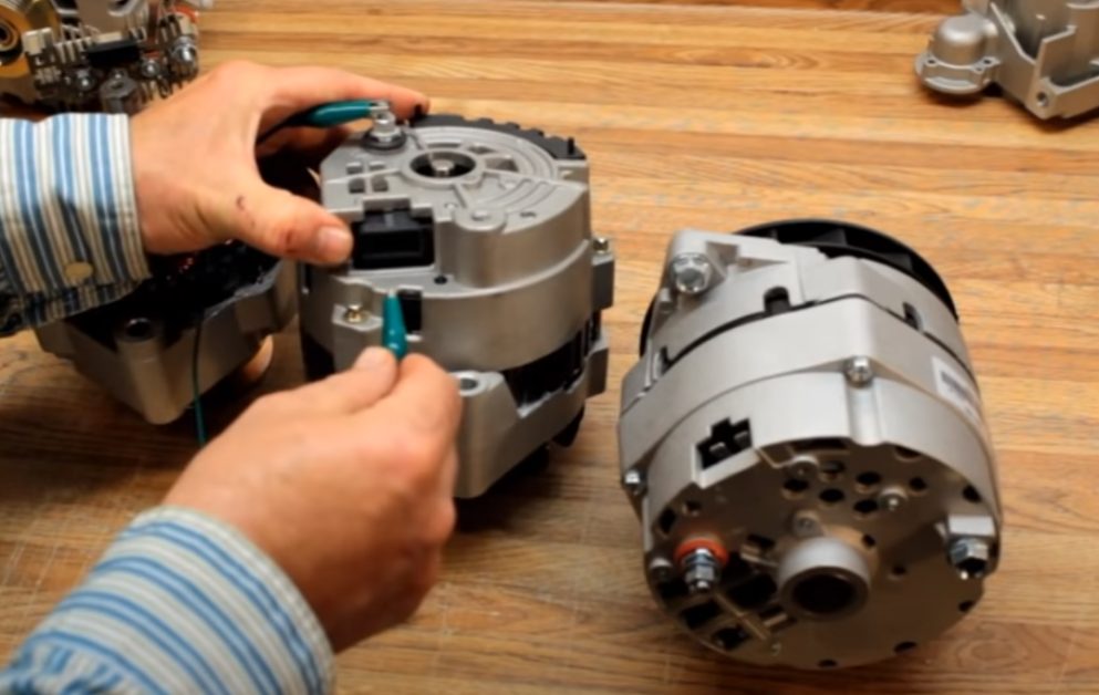
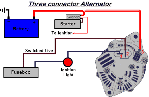
Three-Wire Alternators
A three-way alternator with three pins usually refers to an alternator with an integrated voltage regulator.
The charge output is adjusted according to the voltage level monitored in the ignition and fuse box. It also differs from the two-wire alternator by having a positive wire attached to it using a screw instead of a plug.
This type of alternator has the following wires:
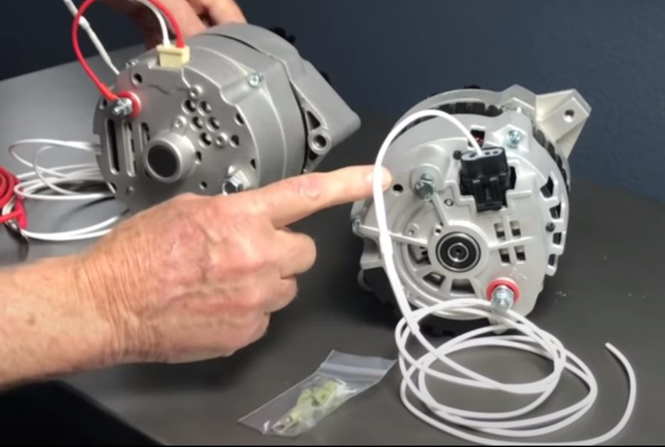
- The alternator’s positive terminal is connected to the battery by the red wire (or via a junction box).
- Two terminal wires (usually adjacent) – The exciter wire is connected to terminal 1 of the regulator, and the ignition input wire is to terminal 2.
- The negative wire is the primary ground connection. It is connected directly to the chassis. Its use deals with interference and improves sensing.
- The sensing wire from the alternator is connected to the battery’s terminal as a link with the regulator. The regulator controls the alternator’s output according to the voltage level.
The additional ignition input wire is linked to the low-voltage warning light beside the ignition switch. The alternator cannot function without it.
Voltage Requirement for Excitation
For a 12-volt ignition system, the excitation process requires at least 13.8 volts of DC.
After regulation, the maximum voltage output of the alternator is usually between 13.5 and 14.8 volts. The power is only supplied to the battery when the voltage is within this tolerable range. A charging battery will, therefore, often measure over 14 volts. (1)
Reference
(1) Allan Bonnick & Derek Newbold. A practical approach to motor vehicle engineering and maintenance. Third edition. Elsevier. 2011.
Video References
alternatorman
Vintage Auto Garage