6 min read
How to Wire an Alternator with an Internal Regulator
If your vehicle’s alternator has an internal regulator, you’ll need to know how to wire it if you’re accustomed to wiring alternators with external regulators.
Alternators with internal regulators usually come in three different types. We will consider those with simple electronic circuitry instead of solid-state and PCM-controlled alternators. Furthermore, I will show how to rewire the internally regulated alternator by replacing the whole unit or repairing it by replacing a crucial component.
When wiring an internally regulated alternator by replacing it with a new, working one, connect the positive output to the battery’s positive terminal, the L point to the ignition switch, and points G and FR to the PCM if applicable.
If repairing an internally regulated alternator, replace the zener diode and connect the battery’s voltage to its cathode end before reattaching it.
More details below.
Alternators with Internal and External Regulators
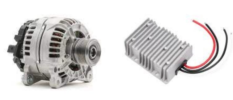
Older alternators have external regulators, whereas newer ones have built-in voltage regulators.
With an internal voltage regulator, you might be tempted to replace the whole unit, but it may be possible to open and fix it, so don’t give up easily.
There are generally 4 types of regulators for alternators:
- Alternators with external regulators – We covered wiring such systems in our article ‘How to Wire a Voltage Regulator to an Alternator.’
- Alternators with internal electronic regulators – This is the type I will show how to wire. It eliminates the need for wiring an external regulator.
- Alternators with solid-state circuitry regulators (without moving parts) regulate the field current and voltage more accurately.
- Alternators with computer-controlled regulation in the PCM (Powertrain Control Module) ensure precise regulation.
Wiring an Alternator with an Internal Regulator
Why You May Need to Wire
You may need to rewire the connection between the alternator and internal regulator when fixing or replacing one of the two or if the wire is damaged.
For example, the alternator might have a constantly higher or lower voltage than normal, or the voltage regulator fails to regulate the voltage within the acceptable range.
Let’s consider two scenarios:
- Scenario 1: Removing and rewiring an internally regulated alternator
- Scenario 2: Repairing and rewiring an internally regulated alternator
Scenario 1 applies if you’re not going to open the alternator to repair it but will replace it with a new one and need to rewire it.
Scenario 2 applies if you’re ready to open the alternator to repair it and will reinstall it after the repair and need to rewire it.
Scenario 1: Removing and Rewiring an Internally Regulated Alternator
Wiring Diagram
Here’s a schematic diagram of a Mitsubishi charging system that uses an internal voltage regulator and a PCM to control the output from an alternator (AC generator):

Follow these steps to remove and rewire an internally regulated alternator:
Step 1: Disconnect the Battery
Disconnect the battery to remove power to the alternator before removing it.
Step 2: Remove the Alternator
Remove the faulty alternator.
Step 3: Connect the Alternator
Connect the new alternator.
Refer to your vehicle owner’s manual for the schematic or wiring diagram for your alternator. The scheme below applies to one particular vehicle, which may differ from yours.
Connect the positive output (B+ above) to the battery’s positive terminal. Then, connect the remaining points as follows:
- Connect point L to the ignition switch
- Connect points G and FR to the PCM
Step 4: Reconnect the Battery
Reconnect the battery after replacing the alternator.
Scenario 2: Repairing and Rewiring an Internally Regulated Alternator
Wiring Diagram
Here’s another typical circuit diagram of an alternator with a built-in electronic regulator:

Here’s a simplified circuit diagram of the regulator part.
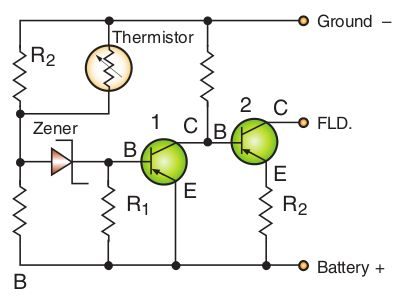
A key component is the zener diode. It blocks current flow until it reaches a certain voltage. So, follow these steps if you need to change it because it’s not operating as it should:
Step 1: Disconnect the Battery
Disconnect the battery to remove power to the alternator before removing it.
Step 2: Open the Alternator
Remove and open the alternator.
Step 3: Replace the Zener Diode
Disconnect and remove the zener diode. Replace it with another working zener diode with the same specifications.
Step 4: Connect the Battery’s Voltage
Connect the battery’s voltage to the zener diode’s cathode and the base (point marked B1) of the first transistor.
Step 5: Close the Alternator
Close and reattach the alternator (see Scenario 1).
Step 6: Reconnect the Battery
Reconnect the battery after replacing the Zener diode.
More About Alternators and Regulators
The Alternator and Charging Circuit
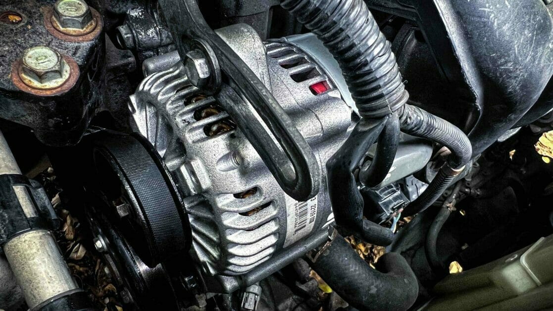
An alternator produces the electrical power required to run a vehicle’s engine and operate its accessories. The battery stores the charge produced.
It generates AC voltage while its current is limited by its operation. The voltage varies proportionally with the field current that flows through the alternator’s rotor.
The exciter wire turns on the alternator unless it is self-exciting. This wire generates the required voltage for the alternator to function and is triggered by the ignition switch. See the wiring diagrams above for the other important wires and points.
The charging circuit containing the alternator uses a wiring harness and includes a voltage or internal regulator, which regulates the voltage output from the alternator before it reaches the battery.
The Voltage Regulator
The voltage or internal regulator tries to maintain the voltage within the range of approximately 13.5 to 14.5 volts when the engine is running (minimum 13.2 to maximum 15.2 volts).
The regulator regulates the voltage by varying the amount of field current through the rotor. When driving with a fully charged battery and no accessories turned on, the regulator’s input (or sensing) voltage is high. The regulator reduces the field current and, thus, voltage output to an appropriate level to trickle charge the battery.
When a heavy load is turned on, the additional draw causes the battery voltage to drop. A low sensing voltage below the regulator’s setting causes the charging voltage output to increase the field current. The regulator will, therefore, increase the current to the rotor to increase the voltage output. The voltage is regulated in this way between the two conditions.
A voltage below the minimum (13.2-13.5V) indicates that the battery is discharging, and a voltage above the maximum (14.5-15.2V) indicates that it is overcharging. In either case, the battery light will show because the voltage will be outside the normal charging system voltage.
References
Website Resources:
- Alternator. https://en.ridex.eu/product/15207976
- Barry Hollembeak. Today’s technician: Automotive electricity & electronics. 7th edition. Cengage Learning. 2017
very helpful, thank you. Explanations and diagrams very good.