10 min read
How to Wire a Breakaway Switch (7 Steps & Test)
Correctly wiring a breakaway switch on a trailer is critical to guarantee proper engagement of the trailer brakes. I have compiled this guide to ensure you wire it correctly with diagrams and tips.
Quick Summary: You wire a break breakaway switch on a trailer after routing its wires to the junction box and attaching the switch and battery box. Then, wire as follows:
Breakaway switch – The blue wire will connect to the blue (break) wires and the white wire with the other white (ground) wires in the junction box. The black wire will connect to the batter’s positive terminal.
Breakaway switch battery – The wire connected to the positive terminal comes from the breakaway switch, and the negative terminal connects to a nearby ground point.
Junction box – Connect the two blue and 16-gauge black wires inside a Wago lever nut
Below, I will go into much more detail, so bear with me!
Method and Requirements
You will require the following items:
- Wire cutter
- Wire stripper
- Wago lever nut (lever type wire connector)
- Spade connector
- Clamp multimeter (or DC meter)
- Screwdriver or gun
Note that the exact procedure for your particular trailer might differ from the details in this article. It would be best if you referred to your trailer’s owner manual.
We will do the wiring in three places: the breakaway switch, the battery box, and the junction box.
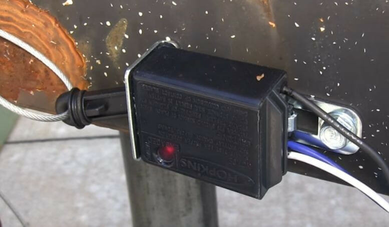
Procedure for Wiring the Breakaway Switch
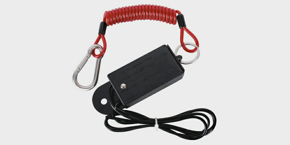
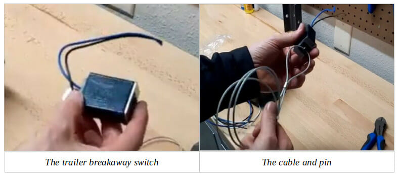
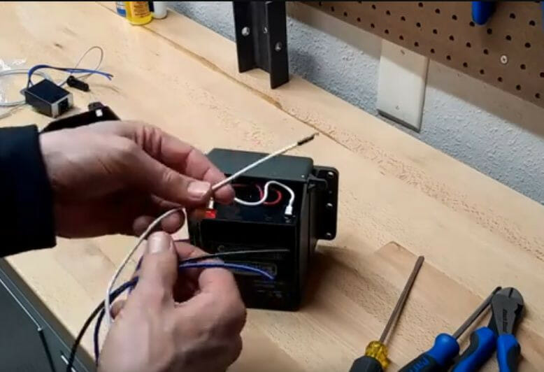
The breakaway switch is shown on the left in the picture below. The kit should also include a cable connected to a pin on the right.
After installing the breakaway switch on the trailer, which we will achieve at the end, insert the pin into the hole on the back of the switch, step 4, further below, under ‘Testing the Breakaway Switch,’ shows when it is removed for testing.
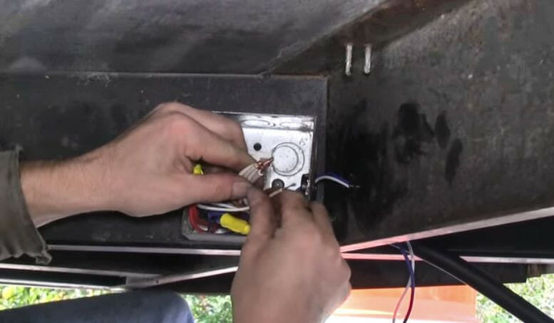
Step 1: Route the Wires
When installing the breakaway switch, insert the wires from it to the junction box, as shown in the picture below. The wires will connect as follows:
- The blue wire will connect with the other blue wires (break leads) – see Step 5 when wiring at the junction box.
- The white wire will connect with the other white wires (ground) – see Step 7 when wiring at the junction box.
- The black wire – see Step 2 when wiring at the battery box.
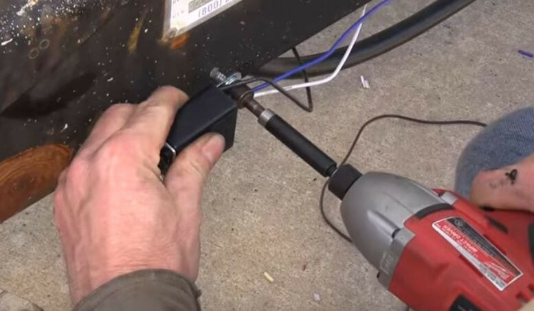
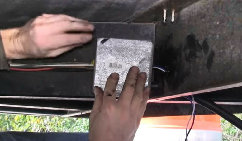
Step 2: Mount the Breakaway Switch
Procedure for Wiring the Battery Box
This particular battery box (in the picture below, with the front cover removed) is designed to mount on the side, but your one may differ as to where it will mount.
The battery supplies power to the brakes if there is an emergency (trailer disconnecting).
Step 1: Mount the Battery Box
Mount the battery box.
We will connect the three wires from the battery box as follows:
- The white wire is the ground wire. Connect it to the corresponding white wire on the trailer connection.
- The black wire (which may be red) connects to the 12 volts from the tow vehicle to keep the battery charged.
- The blue wire is the brake wire that connects to the brake circuit.
Step 2: Crimp and Connect the Black Wire
Route the black wire to the battery box and crimp a spade connector onto its end.
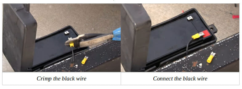
Connect the black wire to the battery’s positive terminal.
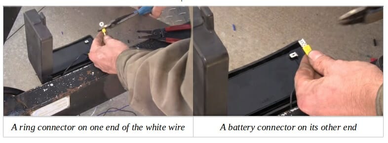
Step 3: Crimp and Connect the White Wire
Crimp a ring connector onto one end of a small white wire and a spade or battery connector on the other end to connect to the battery. It should be long enough to reach from the battery’s negative terminal to a grounding point nearby.
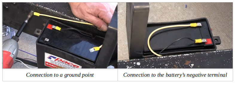
Connect the ring connector end of the small white wire to the nearby grounding point (picture on the left below) and the battery connector end to the battery’s negative terminal (picture on the right below).
Procedure for Wiring at the Junction Box
Step 1: Open the Junction Box
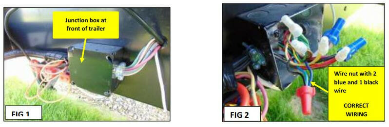
The junction box is usually located at or near the trailer’s front inside a hitch area [Fig. 1].
Remove the screws to open it.
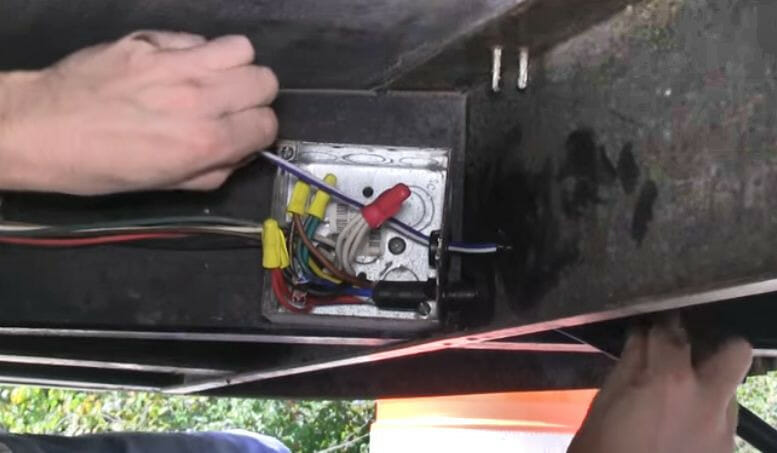
Step 2: Inspect the Junction Box Wiring
Inspect the junction box wiring [Fig. 2]. We will wire the right blue and black wires.
Step 3: Identify the Right Wires
Identify the 2 blue wires [Fig. 3] and the right black wire [Fig. 4] to be connected.
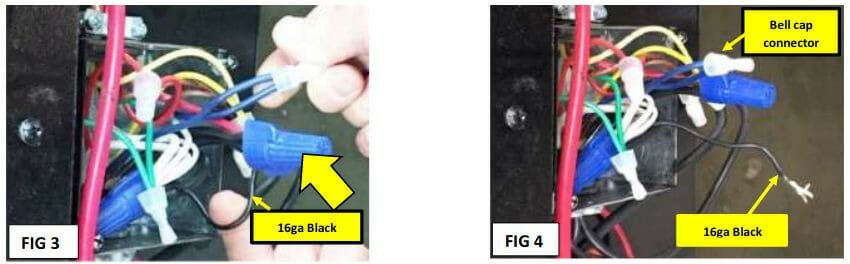
The blue wires are large, so they are easy to identify, but there are 4 black wires. The black wire to connect with the blue ones is the 16-gauge one, which should be thinner than the other three.
Step 4: Strip the Wire Ends
Strip the ends of the 2 blue wires and the 16-gauge black wire you identified in Step 3 using a wire stripper if they are not stripped already. Strip the insulation off approximately 3/8”.
Step 5: Connect the Right Wires
Separate the 16-gauge black wire [Fig. 5] from the other three black wires and insert them with the 2 blue ones into a wago lever nut [Fig. 6]. It does not matter which wire goes into which position; they will all be electrically tied together.
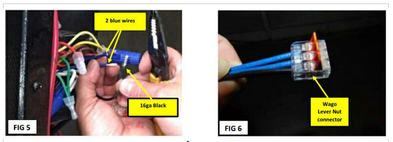
You can use an ordinary wire cap instead of a Wago lever nut, but if you do that, twist the three wires together before twisting them further after putting the cap on. The cap must be large enough to accommodate the three wires, and the connection must be secure, i.e., the cap must not come off easily.
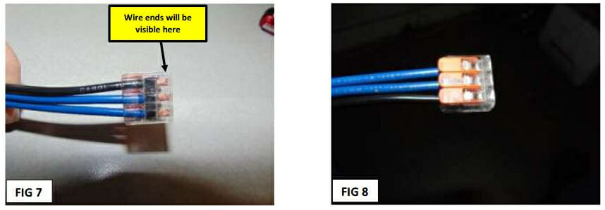
Step 6: Secure the Connection
Ensure the stripped ends of the three wires (2 blue and 1 black) are visible inside the wago lever nut as shown [Fig. 7]. They should extend to the end of the nut.
Also, ensure the levers in the wago lever nut are clamped down to secure the connection of the three wires inside [Fig. 8].
Step 7: Connect the Remaining Wires
Twist the remaining three (non-16ga) black wires with the red wire and cap them with a wire cap.
Also, connect the white wire from the breakaway switch to the other white wires in the junction box for the ground connection (see below). Secure both wire caps.
Testing the Breakaway Switch
Testing the breakaway switch is essential to ensure it will work when needed in an emergency.
Step 1: Apply Power
To test the breakaway switch, apply power to the trailer, either by shore power, the 12V battery, or connecting to the tow vehicle.
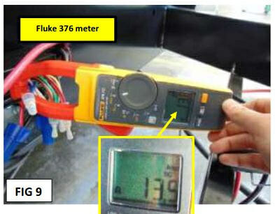
Step 2: Use a Multimeter with a Clamp
Set a multimeter (or DC meter) to measure DC and put its clamp around the two blue wires in the Wago connector.
Step 3: Check the Reading
The reading should remain zero while the breakaway switch remains unactivated.
Step 4: Pull the Breakaway Switch
Pull the breakaway switch as if the trailer had disconnected from the tow vehicle. The picture below shows the breakaway switch being pulled while NOT wired (for demonstration). In a real scenario, the two leads would pull away from the switch and set the trigger inside the switch.
Step 5: Re-Check the Reading
After pulling the breakaway switch, the multimeter reading should be between 12 and 14 amps. If it is, then the wiring was done correctly. If it isn’t, re-check the wiring.
Step 6: Replace the Cover
Tuck all the wiring inside the junction box at the end and close the cover.
References
OminEco Trailer Breakaway Switch. https://www.amazon.com/OminEco-Trailer-Breakaway-Switch-Electric/dp/B09QSL2GT6/
Jayco. Emergency brake breakaway switch wiring. https://static.nhtsa.gov/odi/rcl/2019/RCRIT-19V516-3726.pdf
Video References:
Etrailer.com
SyEnsability