9 min read
How to Wire a 12V Relay (3 Main Steps & Guide)
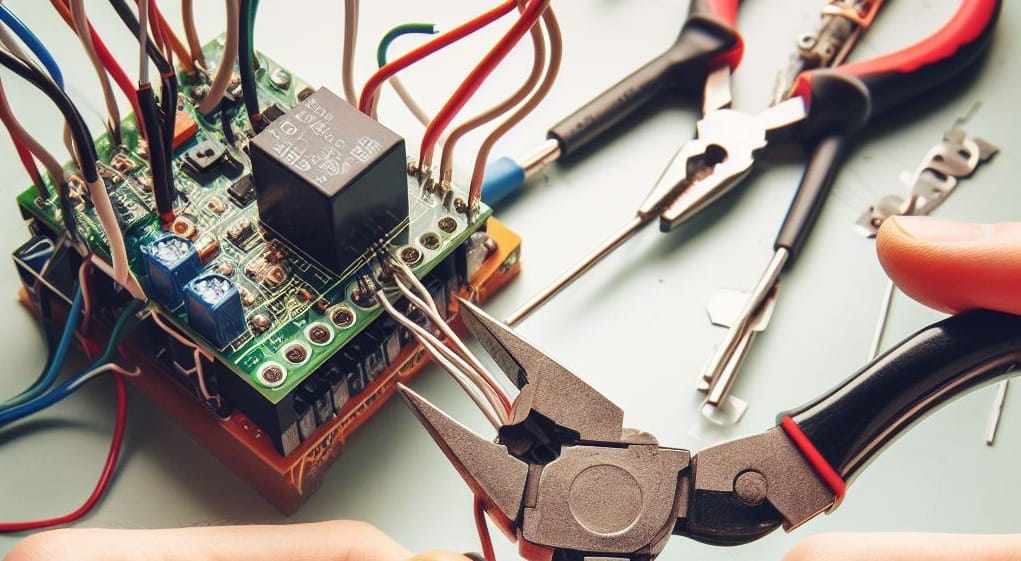
A relay switch has multiple terminals, which can be confusing if you’ve never wired one.
A 12V relay is no exception. However, you can learn to wire a 12V relay using this guide. Not only that, but I’ve also explained how relays work, which should make it easier to ensure you’ve wired it correctly.
Quick Summary: To wire a 12V relay, connect the 12V power source to Pin 30, the trigger control circuit to pins 85 and 86, the load to Pin 87, and, optionally, an alternative load to Pin 87a.
I’ve included a couple of samples of how a 12V relay would be used together with circuit diagrams.
12V Relays
A relay switch controls a higher-current circuit using a low-current trigger.
Relays are commonly used in motor vehicles, such as for sending an ignition switch signal to the starter motor and for controlling large motors with a high current draw.
The type of relay we are considering here has a 12V DC coil voltage, which usually has a contact amperage rating of up to 5A, as in an automotive relay.
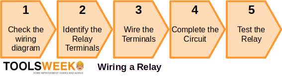
Wiring a 12V Relay
When wiring a 12V relay, check the wiring diagram and identify the terminals.
Then, wire the relay terminals and complete the rest of the circuit accordingly. Here are the steps:
The relay will connect to three other components in the circuit:
- A power source
- A controller, such as a switch
- The load to be controlled
Follow these steps:
Step 1: Check the Wiring Diagram
12V relays normally have a wiring diagram printed on them like the one below to ensure you make the connections properly.
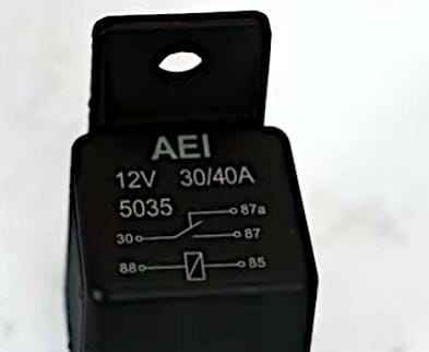
In a typical 5-pin 12V relay:
- Pins 85 and 86 receive the trigger current. They might be marked ‘COIL’. Connect either one to a switch and the other to the negative terminal of the power source.
- Pin 87 connects to the device you want to control. When switched on, this terminal connects to the power source terminal inside the relay and powers the load.
- Pin 30 might be marked as ‘COM’ or ‘COMMON’. It will connect to the power source.
- The extra Pin 87a is normally closed. It’s not normally used unless you want the load to get power when the relay is switched off. So, use either Pin 87 or 87a, as per your preference.
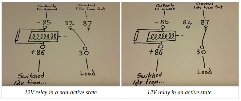
One of the two control pins (85 or 86) must be grounded. The other goes to a switched power source.
The 12V relay operates by connecting the load attached to Pin 30 to Pin 87, which has a constant 12v from the battery. The switch changes over to Pin 87a when in a non-active state. Refer to the diagrams below to see the difference between the relay being active (or energized) and non-active.
Step 2: Identify the Relay Terminals
Relay pin (or terminal) layouts and their functions are not standard, so that they may vary between manufacturers.
Below is a 4-pin (right) and 5-pin (left) 12V relay. The difference is that 4-pin relays have only a “normally open” terminal, whereas a 5-pin one has an additional “normally closed” terminal.
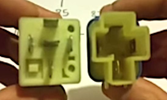
A typical 5-pin 12V relay will have the following connections:
| Pin | Connection |
| 30 | Power source or battery feed (common) |
| 85 | Control circuit (coil terminal) |
| 86 | Control circuit (coil terminal) |
| 87 | Load device (normally open terminal) |
| 87a | Normally closed terminal |
Step 3: Wire the Terminals
Wire the relay’s terminals according to the wiring diagram, considering the available pins, markings, and the circuit’s purpose.
Usually, you would wire the 12V relay terminals as follows:
- Connect the 12V power source to Pin 30.
- Connect the (trigger) control circuit to pins 85 and 86.
- Connect the load (you want to control) to Pin 87 to be normally open when the relay is active.
- Connect the alternative load (you want to control when the main load is off) to Pin 87a, if applicable, to be normally closed when the relay is active.
Step 4: Complete the Circuit
Wiring the relay switch alone may not be enough to complete the circuit.
If there are other components on the circuit, wire them before switching the circuit.
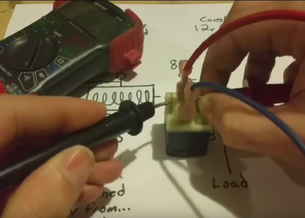
Step 5: Test the Relay
Besides checking to ensure you’ve wired the relay and the rest of the circuit correctly, the continuity test is one important test to ensure the relay itself is working.
There should be continuity between the 30 and 87 terminals when the relay is active. Attach a multimeter’s probes (set to read in ohms) to these two terminals to confirm low resistance.
Sample Applications
12V DC Fan
When wiring a 12V relay to a fan, the setup should look something like this:
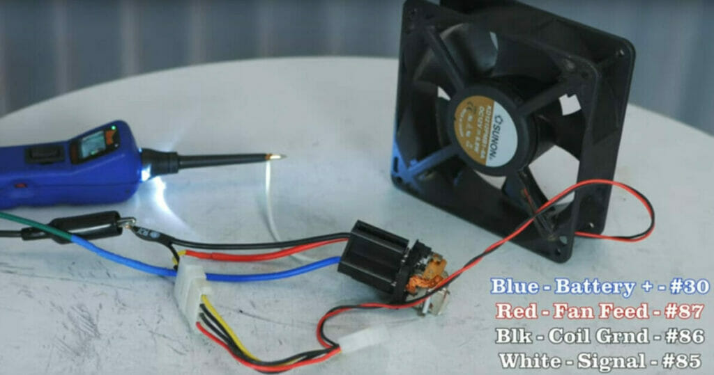
The wires are connected to the four pins on this relay as follows:
- The green wire on the left side sends power to the blue wire on the relay socket (Pin 30).
- The red wire is the battery power out to the fan (Pin 87) once the relay is energized.
- The black wire on the fan connector and socket (Pin 86) provides grounding for the relay and fan.
- The white wire attached to Pin 85 is the control circuit to the relay.
If it’s a 5-pin relay, you don’t need to use Pin 87a.
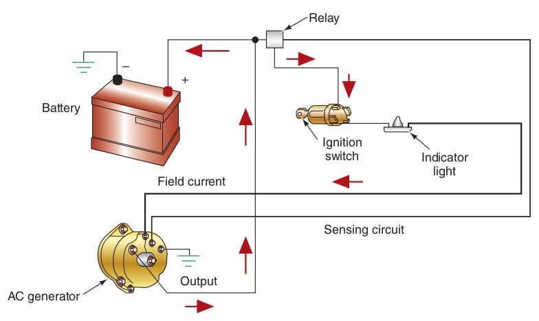
Starter Relay
A vehicle’s electrical charging circuit resembles the diagram below, which uses a starter relay connected near the ignition switch.
Turning the ignition switch on sends an electrical signal to the relay, activating the charging circuit.
FAQs on Wiring a 12V Relay
Q: Break it down for me: How does this relay magic work?
Imagine a relay like that light switch on your wall. Flick it on, and BAM! Lights up the whole room. It’s the go-between for your small action and big result.
Q: So, with all these pins and numbers, what’s the relay’s game plan?
You got your Pin 30 (that’s where the power hangs out), Pins 85 and 86 (they’re the relay’s brainpower – the control circuit), Pin 87 (that’s where your load’s at), and Pin 87a (the cool cousin who’s normally just chilling out, but ready to jump in).
Q: I’m gearing up! How do I wire this bad boy up?
- Easy as pie! Hook the 12V power to Pin 30.
- Get those control circuits rocking on Pins 85 and 86.
- Your load? That goes to Pin 87.
- Do you have an alternative load? Pin 87a’s got your back.
Q: Okay, but how do I know my relay’s rocking and rolling correctly?
Test drive time! You will want to check the connection between 30 and 87 when that relay’s in action. Grab that multimeter and see if they’re talking!
Q: So, there’s a 4-pin relay and a 5-pin relay? What’s the difference?
You got it! The 4-pin is a straight shooter with a “normally open” terminal. But the 5-pin? It’s got an extra move with its “normally closed” terminal.
Q: Relays: Are they all born equal?
Not quite, my friend! While they all have the same spirit, their pin layouts can dance to a different tune, depending on the maker. Always keep an eye on that specific relay’s blueprint.
Q: What’s the 411 on Pin 87a?
Our buddy, Pin 87a, is there when you want to keep the party going, even when the relay’s taken a break.
Q: Where can I get a visual? I’m a see-it-to-believe-it kind of person!
You and me both! Dive into the article, and you’ll find some rockin’ vids by HotRodHippie, and Blaser Builds that show you the ropes.
Q: Why do cars love relays so much?
Like how we love a good power tool in a reno, cars use relays to get those big jobs done with a tiny switch without burning the whole place down!
References
Website Resources:
- Barry Hollembeak. Today’s technician: Automotive electricity & electronics. 7th edition. Cengage Learning. 2017
Website References:
Blaser Builds
HotRodHippie