9 min read
How to Wire a 4-Pin Relay (Step-by-Step Guide)
Wiring a 4-pin relay can seem complicated due to the number of pins, but it’s easy once you understand what the pins are for.
This guide will help you identify the 4 pins, understand their function, and take you step-by-step through wiring a 4-pin relay. It’s an easy task that you can manage on your own.
Wiring a four-pin relay is a simple three-step process:
- Connect Pin 85 to the ground.
- Connect pins 86 and Pin 87 as the switching pins.
- Connect a 12V battery to Pin 30 of the relay via a fuse.
Continue reading below for more detailed instructions, including three specific examples to illustrate the procedure (12V fan, vehicle driving lights, and reverse lights).
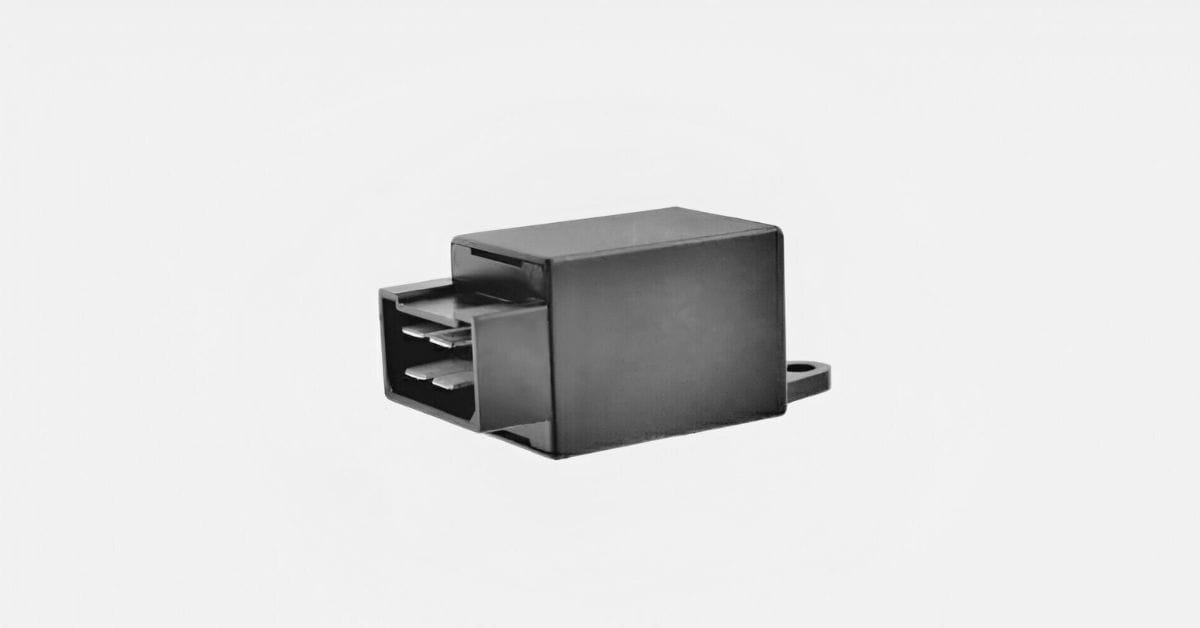
4-Pin Relays
A relay is an electrically operated switch used in electronic circuits to regulate and control multiple operations.
It works on the principle of electromagnetism to control its inner contacts. With the help of a relay, you can control a high-current circuit via a low-current one. 4-pin relays are commonly used for controlling fog lights, LED lights, and automotive electronics.
Four-Pin Relay Pins
First, let’s identify the 4 pins on a 4-pin relay and understand their function.
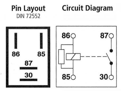
The 4 pins are typically numbered 30, 85, 86, and 87, as shown below for 2 4-pin relays.
Procedure for Wiring a 4-Pin Relay
In general, always check the wiring diagram when wiring a relay.
It’s usually printed on it, and the terminals are normally marked with numbers, as shown above. The relay will connect to three other components in the circuit:
- A power source
- A controller, such as a switch
- The load to be controlled
You must know which other component connects with which terminal on the relay. The connections are usually as indicated in the table below:
| Pin | Connection |
| 30 | Power source or battery feed (common) |
| 85 | Control circuit (coil terminal) |
| 86 | Control circuit (coil terminal) |
| 87 | Load device (normally open terminal) |
In a 4-pin relay:
- Pins 85 and 86 receive the trigger current. They might be marked ‘COIL’. Connect either one to a switch and the other to the negative terminal of the power source.
- Pin 87 is connected to the device you want to control. When switched on, this terminal connects to the power source terminal inside the relay and powers the load.
- Pin 30 might be marked ‘COM’ or ‘COMMON’ instead. It connects to the power source.
One of the two control pins (85 or 86) must be grounded. The other goes to a switched power source. When wired to a fan, for example, the wiring setup should look something like this:
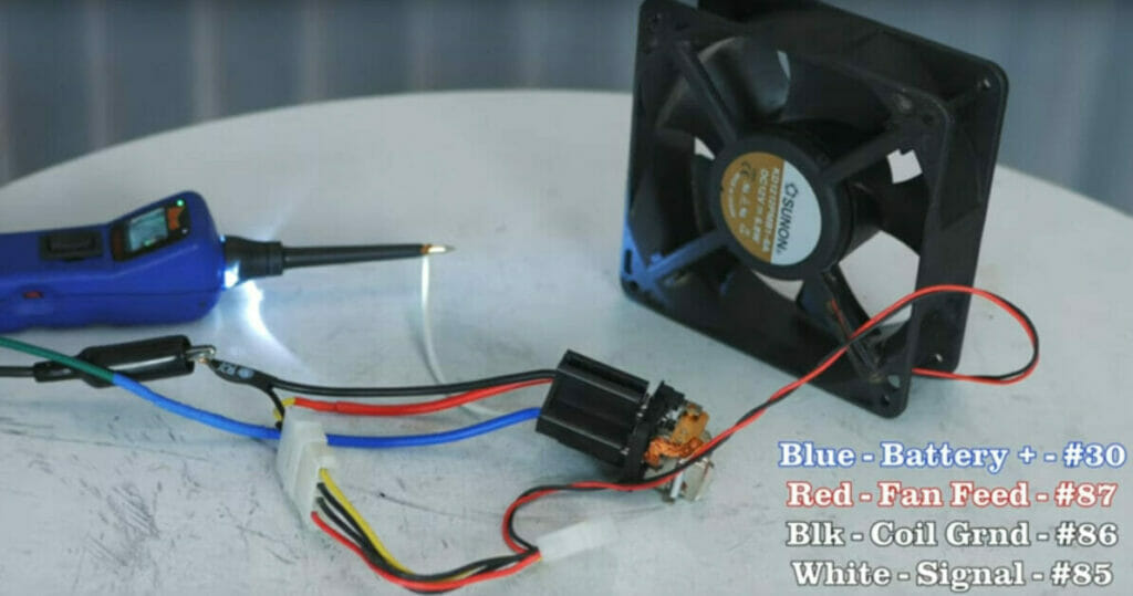
The wires are connected to the four pins on this 4-pin relay as follows:
- The green wire on the left side sends power to the blue wire on the relay socket (Pin 30).
- The red wire is the battery power out to the fan (Pin 87) once the relay is energized.
- The black wire on the fan connector and socket (Pin 86) provides grounding for the relay and fan.
- The white wire attached to Pin 85 is the control circuit to the relay.
You will understand the wiring procedure better by looking at a few more specific setups where a 4-pin relay is typically used.
Wiring a 4-Pin Relay for Driving Lights
This step-by-step guide will guide you in wiring a 4-pin relay for driving lights if you want to learn more about how to wire one. It’s a simple three-step process:
- Correctly locate the headlight wires
- Prepare the ground connection
- Connect the 4-pin relay
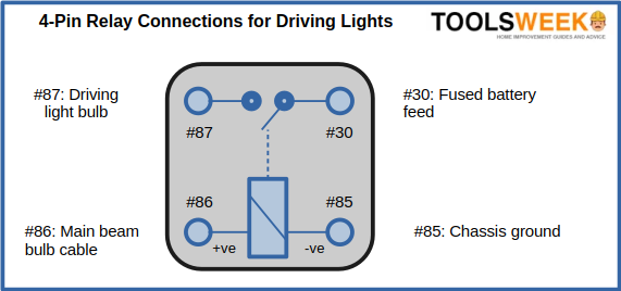
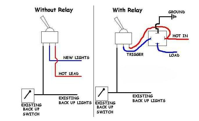
Circuit Diagram
Below is a circuit diagram for a typical 4-pin relay for wiring driving lights.
Step 1: Correctly Locate the Headlight Wires
Firstly, identify the wires from the driving lights.
For easy identification, the power wire is normally red, and the ground wire is black. Ensure you identify the two wires correctly before proceeding to the next step.
Step 2: Prepare the Ground Connection
The vehicle chassis’ ground should be connected to the negative ground wire.
Do not let the red wire be close to any of the engine’s moving parts to avoid any issues.
Step 3: Connect the 4-Pin Relay
In this step, we will wire the 4-pin relay.
To wire a four-pin relay for driving lights, the first step is to use a fuse to connect the 12V battery to Pin 30 of the 4-pin relay.
We connect the relay via a fuse instead of establishing a direct connection with the battery to avoid any over-currents. Thus, connecting via a fuse is much safer and more practical. If there are any issues in the driving light circuit, the fuse will protect the lights and circuits from burning due to intolerable current levels.
Note that Pin 86 and Pin 87 of the relay switch pins and Pin 85 connect to the ground.
Using this 4-pin relay, you can switch on the main beams’ lights of the driving light by alternating the battery connections with either Pin 86 or Pin 87 on the relay.
Here’s a summary of the 4 connections:
- Connect Pin 85 of the relay to the vehicle body, as mentioned under Step 2.
- Connect Pin 86 to the switch to be operated by the driver while driving the vehicle.
- Connect the positive red wire to Pin 87 of the relay.
- Connect the 12V battery installed in the vehicle or cabin to Pin 30 of the relay.
Please note that using a fuse, you need to connect the 12V battery to the relay’s Pin 30. Don’t connect it directly.
A fuse is used as a medium to ensure no damage is caused in electrocution due to high voltages of current flowing, which may happen with a short circuit in the 4-pin relay setup.
Your 4-pin relay is set up and ready to use.
Wiring a 4-Pin Relay for Reverse Lights
Reverse lights are wired following the same procedure outlined above for driving lights, with one exception.
For reverse lights, the only change to be made in the relay is that the positive of reverse lights connects to Pin 87. To quickly recap the wiring procedure for a 4-pin relay for reverse lights:
- Pin 85 connects to the ground.
- Pin 86 connects to the switch to be operated by the vehicle’s driver.
- Pin 87 connects to the positive connection from the reverse lights.
- Pin 30 of the relay connects to the vehicle’s 12V battery via a fuse.
Once again, don’t connect Pin 30 directly to the 12V battery because it can be dangerous if a short circuit occurs. It can harm you and the vehicle. Follow these instructions, and you can set up a relay for reverse lights safely in no time using a fuse.
Why Use a Four-Pin Relay
There are various relays, including 4-pin and 5-pin relays and more.
Have you ever wondered why we use a 4-pin relay? Let’s consider its use for controlling driving lights.
Why Use a Four-Pin Relay for Driving Lights?
It is best to put a 4-pin relay system in place to steer clear from harmful and damaging voltage outside your driving zone or cabin.
The relay helps contain the high voltages required by the headlights and is delivered by the battery within the engine area. Thus, the relay provides a safe closure space for all the raging voltages and currents.
But, if you observe how a relay works, it is like a switch controlled by another switch. The switches installed in the vehicle’s driver’s seating area or the cabin’s interior work on extremely low voltages. The low voltage is not powerful enough to cause any harm to the vehicle’s driver and its components. Thus, being an electromagnet, this switch revs up the relay’s power to control the headlight circuits powered by higher voltages and currents.
Thus, it is evident how a low-current circuit takes control of a high-current circuit to stabilize a vehicle’s safety and security needs. The relay facilitates this process as a much-needed intervention to avoid potential disasters.
RELATED 3 Pin Horn Relay Wiring Diagram
References
Website Resources:
- electrocution. https://www.mayoclinic.org/first-aid/first-aid-electrical-shock/basics/art-20056695
- technical help. https://www.thebalancecareers.com/tech-support-skills-list-2063774
Video References
HotRodHippie
Rocky X TV