11 min read
How to Wire a Relay (Circuit, Connection, Diagram)

In this article, I will show you how to wire a relay, don’t worry; it’s not as hard as it may seem.
Quick Summary; A relay usually has a wiring diagram or datasheet printed on it. Identify the relay terminals and follow that diagram to know where to connect the wires, as there is no standard across all relays and models. It will connect to a power source, a controller such as a switch, and the load to be controlled.
I’ve given several examples of how to wire a relay for different types and usage situations, introduced them, explained their pinouts, and shown sample configurations below.
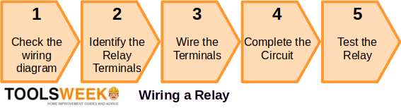
Wiring a Relay
When wiring a relay, check the wiring diagram first and identify its terminals.
Then, wire the relay terminals and complete the rest of the circuit accordingly. Here are the steps:
Relay pin layouts and functions are not standard, so they may vary between manufacturers. Always check the markings on the component or the accompanying datasheet or conduct a continuity test.
The relay will connect to three other components in the circuit:
- A power source
- A controller, such as a switch
- The load to be controlled
Example Wiring and Pinouts
Here’s an example of a wiring diagram printed on a relay:
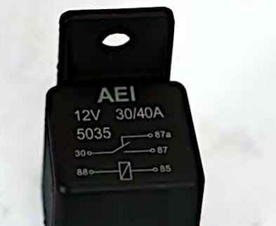
For this particular relay, the connections are as follows:
| Pin | Connection |
| 30 | Power source or battery feed (common) |
| 85 | The control circuit (coil terminal) |
| 86 | Control circuit (coil terminal) |
| 87 | Load device (normally open terminal) |
| 87a | Normally closed terminal |
In this 5-pin relay:
- Pins 85 and 86 receive the trigger current. They might be marked ‘COIL.’ Connect either one to a switch and the other to the negative terminal of the power source.
- Pin 87 is connected to the device you want to control. When switched on, this terminal connects to the power source terminal inside the relay and powers the load.
- Pin 30 might be marked as ‘COM’ or ‘COMMON.’ It will connect to the power source.
- The extra Pin 87a is normally closed. It’s not normally used unless you want the load to get power when the relay is switched off. So, use either Pin 87 or 87a, as per your preference.
One of the two control pins (85 or 86) must be grounded. The other goes to a switched power source. When wired to a fan, the wiring setup should look something like this:
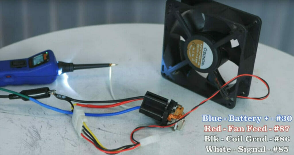
The wires are connected to the four pins on this relay as follows:
- The green wire on the left side sends power to the blue wire on the relay socket (Pin 30).
- The red wire is the battery power out to the fan (Pin 87) once the relay is energized.
- The black wire on the fan connector and socket (Pin 86) provides grounding for the relay and fan.
- The white wire attached to Pin 85 is the control circuit to the relay.
Examples of Uses and Wiring Diagrams
Here, I give some examples of typical uses of relays and the following wiring diagrams.
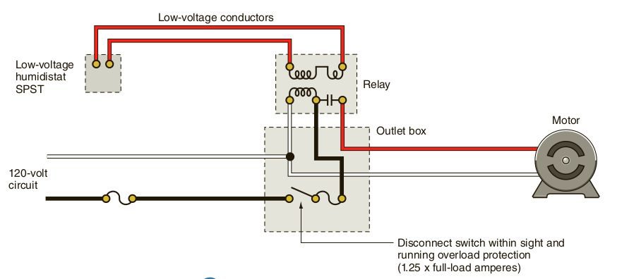
Humidistat
Let’s consider a humidistat with and without a relay. Without it, the circuit may look something like this:
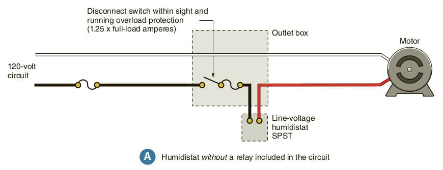
The addition of a relay would make the circuit something like this:
Electric Baseboard Heating Unit
A relay is useful to control a load’s ampere rating to not exceed the line-voltage thermostat rating, with a 2-pole thermostat as the means for disconnection.
Note that line-voltage thermostats are usually ampere rated for non-inductive resistive loads, so you may need to convert watts to amperes to find the right size thermostat. Apply the formula I = P / V, where V is typically 120 or 240 volts.
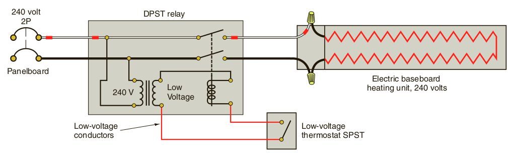
The relay’s line-voltage contacts are used to switch the heater load.
3-Wire Submersible Pumps
A starting relay is typically found in 3-wire pumps, which, unlike a 2-wire one, have a controller above ground.
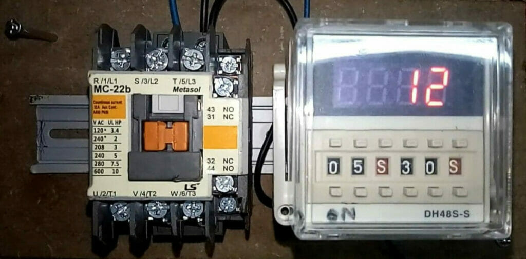
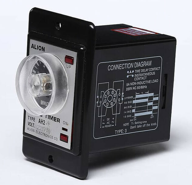
A timer relay is especially useful, as it allows you to set a specific time interval for operation without forgetting to turn the pump off manually. The relay should come with a wiring diagram. Here’s such a diagram for one particular model in a particular switch position:
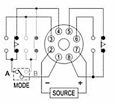
The wiring technique is similar to how you would wire an outlet. The relay has screw terminals to which you connect the right wires.
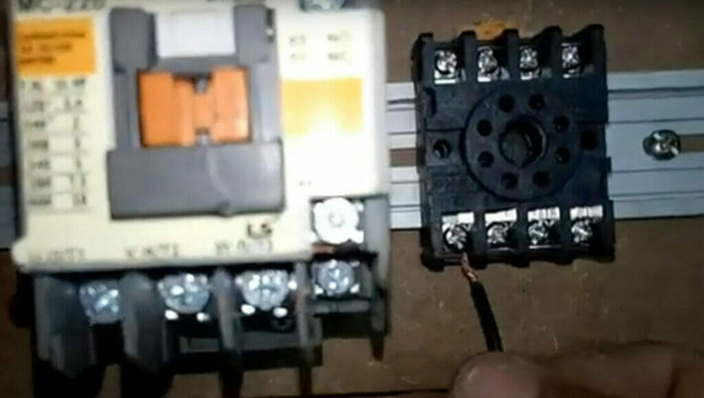
As you can see from the wiring diagram, pins 2 and 7 will connect to the power source, so connect the AC power source to pins 2 and 7. After the wiring is done, you set the timer module in place over the relay to look like this:
Starter Relay
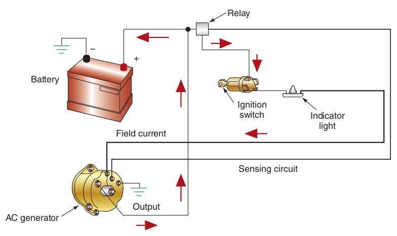
A starter relay is an important part of the electrical charging circuit in many vehicles.
When you turn the ignition switch, the relay sends an electrical signal to a relay close to the starter motor. It is typically connected, as shown in the circuit diagram below.
About Relays
What They Are
A relay is found in many home appliances, wherever a substantial load has to be switched on and off, whether it’s a control switch, a thermostat, or an electronic circuit.
It is “an electromagnetic device with one or more sets of contacts that change position by the magnetic attraction of a coil to an armature” [US Navy, 1998]. It is technically called an ‘electromagnetic armature relay’ to distinguish it from a (faster and more reliable) solid-state one.
In this article, I will show you how to wire the first mechanical type with examples in different home and vehicle circuits.
Purpose
A relay enables an electric pulse or signals to switch a separate electricity flow on or off. [Platt, 2013]
It usually uses a low voltage or current to control a higher one, so you can operate one with even a small switch and use a small-gauge wire (up to a point).
Uses
Having a relay is particularly useful in the following example situations:
- When the wiring becomes very lengthy
- Large motors with a high current draw
- When the load current could exceed the current rating of a line-voltage thermostat
- Sending an ignition switch signal to a vehicle’s starter motor
Recognizing Relays
Here are some common DC-powered relays and a timer relay:
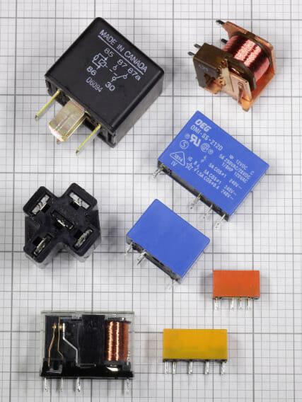
Note that the above relays have at least three pins. Their configuration is specified for regular switches, typically SP, DP, 3P, and 4P, indicating the poles (1 to 4). ST or DT is also specified, indicating single- or double-throw switching.
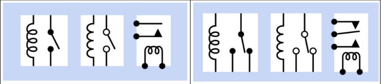
Schematic Symbol
When following a circuit diagram, you will need to recognize the schematic symbol of a relay.
Simple Pin Configurations
Below is a sample of simple DPDT relay pin configurations.
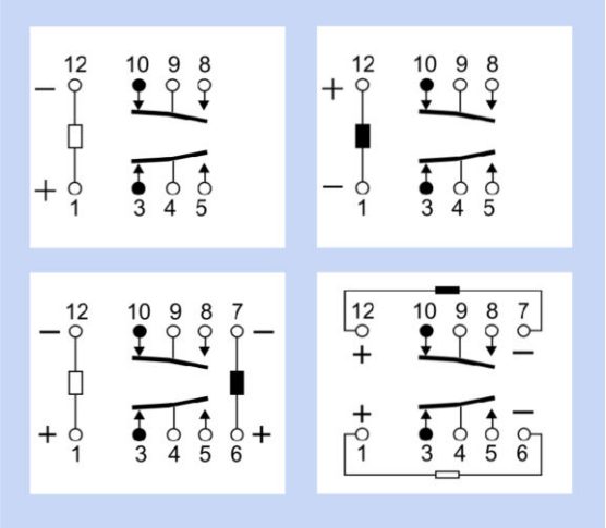
Note the following:
- The rectangle is the relay coil.
- The circles are the pins.
- Black indicates an energized state.
- White indicates a non-energized state.
- The arrows show the fixed contacts.
- Bent lines show possible connections between the poles and other contacts.
Types of Relays
Before wiring a relay, you should know which type of relay is suitable. Take its coil voltage, current draw, and voltage into account.
| Relay | Typical Ranges | Common Uses |
| Low/Small-signal relay | Coil voltage: 5-24VDC, drawing ~20mA; max. current for non-inductive loads: 1-3A. | Small footprint situations |
| Reed relay | Coil voltage of 5VDC (up to 24V in through-hole PCB versions); coil resistance 500-2000 ohms; contact rating up to 0.25A at 100V. | Coil voltage: 12-24VDC or 24-230VAC; timed intervals: 0.1 seconds to 9999 hours; contact rating 5-20A with 125-250V AC or DC. |
| Timer relay | Coil voltage: 12-24VDC or 24-230VAC; timed intervals: 0.1 seconds to 9999 hours; contact rating 5-20A with 125-250V AC or DC. | Industrial processes |
| Automotive relay | Coil voltage 12VDC; contact rating 5A at up to 24VDC. | 12VDC only |
| General purpose/industrial relay | Coil voltage 12VDC; contact rating 5A up to 24VDC. | Octal sockets accept relays with an octal base |
When buying a relay, you might come across these terms, so I’ve explained what they mean:
- ‘Must Operate By’ voltage – minimum voltage the relay needs for activation
- ‘Must Release By’ voltage – maximum coil voltage the relay ignores
Remote Control Relays
A remote control relay has two on/off coils to allow the relay plunger to move positively in either direction (without requiring a spring) and a common center tap.
- In the ON position, current passes through the ON coil and causes the movable core to shift, closing the contacts and powering the load.
- In the OFF position, current passes through the OFF coil, which moves the core and opens the contact to disconnect the power to the load.
Remote control relays can control around 20 amps of lighting or inductive loads at 110/277 AC volts. [US Navy, 1998]
References
Charles Platt. Encyclopedia of electronic components. Vol 1: power sources and conversion. O’Reilly. 2013
Barry Hollembeak. Today’s technician: Automotive electricity & electronics. 7th edition. Cengage Learning. 2017
Ray C. Mullin, Phil Simmons. Electrical Wiring Residential. Cengage Learning. 2017
US Navy. Construction electrician is basic: nonresident training course. Navedtra 14026. United States Navy
Printed wiring diagram for a timer relay. https://www.aliontimer.com/product/asy-industrial-timer-relay/
Timer relay. https://www.aliontimer.com/timer-relay/
Video References:
HotRodHippie
Ideal Electrical