6 min read
How to Test a Map Sensor with a Multimeter (Step-by-Step Guide)

The manifold absolute pressure (MAP) sensor detects air pressure in the intake manifold and allows the vehicle to change the air/fuel ratio. When a MAP sensor malfunction, it can impair engine performance or cause the check engine light to illuminate. It uses a vacuum to monitor the pressure in the intake manifold. The higher the pressure, the lower the vacuum and the voltage output. The higher the vacuum and the lower the pressure, the higher the voltage output signal. So, how do you test a MAP sensor with a digital multimeter?
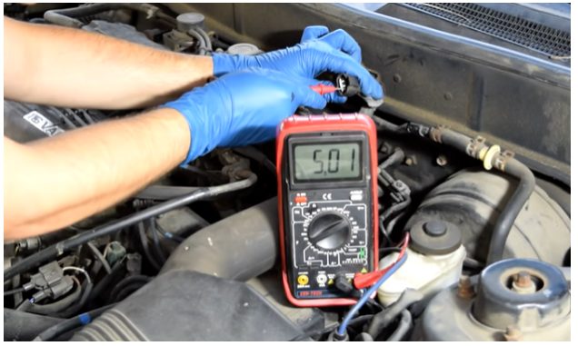
In general, to test a MAP sensor with a multimeter: connect the multimeter’s black lead to a good ground or bind it to the MAP sensor. Turn on the ignition key while the engine is off. Then connect the red lead to the MAP sensor’s electrical connector with three wires in the center. The multimeter’s reading should be between 4.5 and 5 volts. Afterward, start the engine, and the voltage displayed at level or near should be.5 to 1.5 volts. As altitude climbs, the voltage decreases. If the voltage on either test changes significantly, the MAP sensor is fried and replaced.
This step-by-step learning guide will teach you to test MAP sensors with digital multimeters.
What Does a MAP Sensor Do?
A MAP sensor measures the amount of air pressure in proportion to the vacuum inside the intake manifold, either directly or through a vacuum hose. The pressure is then converted into a voltage signal, which the sensor sends to the power control module (PCM), your car’s computer. (1)
The sensor needs a 5-volt reference signal from the computer to return the movement. Changes in vacuum or air pressure in the intake manifold change the electrical resistance in the sensor. It may raise or decrease the voltage of the signal to the computer. The PCM adjusts fuel supply to the cylinders and ignition timing based on the current check engine load and speed using information from the MAP sensor and other sensors.
How to Test a Map Sensor with a Multimeter
#1. Preliminary Check
Make a preliminary check before testing a MAP sensor. Depending on your installation, the sensor attaches to the intake manifold through a rubber hose; otherwise, it connects directly to the intake.
When issues emerge, the vacuum hose is most likely to blame. Sensors and hoses in the engine compartment are subjected to high temperatures, possible contamination from oil and gasoline, and vibration, which can impair their performance.
Examine the suction hose for:
- kinks
- weak connections
- cracks
- swelling
- softening
- hardening
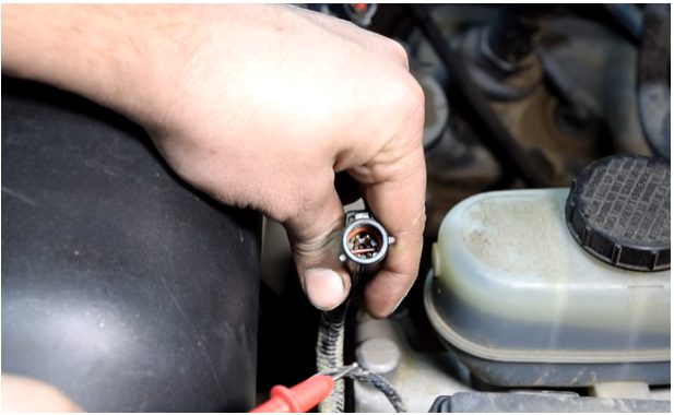
Then, inspect the sensor’s body for damage, and ensure that the electrical connector is tight and clean and the wiring is in excellent working order.
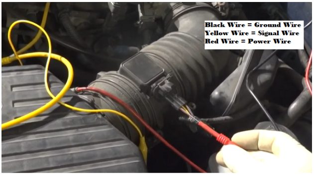
The ground wire, signal wire, and power wire are the three most important wires of the car’s MAP sensor. However, some MAP sensors have a fourth signal line for the intake air temperature controller.
It required that all three wires function well. It is critical to examine each wire individually if the sensor fails.
#2. Power Wire Test
- Set the voltmeter settings on the multimeter.
- Turn ON the ignition key.
- Connect the multimeter’s red lead to the MAP sensor’s power (Hot) wire.
- Connect the multimeter’s black lead to the battery’s ground connector.
- The displayed voltage should be approximately 5 volts.
#3. Signal Wire Test
- Turn ON the ignition key.
- Set the voltmeter settings on the digital multimeter.
- Connect the multimeter’s red lead to the signal wire.
- Connect the multimeter’s black lead to the ground.
- Because there is no air pressure, the signal wire would indicate a value of roughly 5 volts when the ignition is turned on, and the engine is turned off.
- If the signal wire is functioning correctly, the multimeter should read about 1-2 volts when the engine is turned on. The signal wire’s value changes because air begins to move within the intake manifold.
#4. Ground Wire Test
- Keep the ignition switch on.
- Set the multimeter to the continuity tester set.
- Connect the digital multimeter’s two leads.
- Because of the continuity, you should hear a beep sound while connecting both leads.
- Then, connect the multimeter’s red lead to the ground wire of the MAP sensor.
- Connect the multimeter’s black lead to the battery’s ground connector.
- If you hear a beeping sound, this shows continuity, indicating that your ground wire is functioning correctly.
#5. Intake Air Temperature Wire Test
- Set the multimeter to voltmeter mode.
- Turn ON the ignition key.
- Connect the multimeter’s red lead to the signal wire of the intake air temperature sensor.
- Connect the multimeter’s black lead to the ground.
- The IAT sensor value should be about 1.6 volts at 36 degrees Celsius air temperature. (2)
Signs of a Bad MAP Sensor
How do you identify if you have a bad MAP sensor? The following are the significant issues to be aware of:
Fuel Economy is Substandard
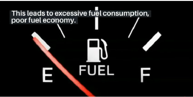
If the ECM senses low or no air, it assumes the engine is under load, dumps more gasoline, and advances the spark timing. It results in high gasoline consumption, poor fuel efficiency, and, in extreme cases, explosion(very rare).
Inadequate Power
When the ECM detects a high vacuum, it assumes that the engine load is low, reduces fuel injection, and retards spark timing. Moreover, fuel consumption will be diminished, which appears to be a positive thing. However, if not enough gasoline is burned, the engine may lack acceleration and driving power.
Hard to Start
Consequently, an abnormally rich or low mixture makes starting the engine difficult. You have a MAP sensor problem if you can only start the engine when your foot is on the accelerator.
Emission Test Fails
A faulty MAP sensor might increase hazardous emissions because fuel injection is not proportional to engine load. Excessive fuel consumption results in increased hydrocarbon (HC) and carbon monoxide (CO) emissions, whereas inadequate fuel consumption results in higher nitrogen oxide (NOx) emissions.
Take a look at some of our related articles below.
- How to use a Cen-Tech digital multimeter to check voltage
- How to test 3-wire cam sensor with multimeter
- How to test ignition control module with multimeter
References
(1) PCM – https://auto.howstuffworks.com/engine-control-module.htm
(2) temperature – https://www.britannica.com/science/temperature