15 min read
How to Test a Crankshaft Position Sensor with a Multimeter (2 Tests per Type)
If your car struggles to start, there might be a problem with your crankshaft position sensor (CKP) sensor.
A CKP sensor endures vibration and heat while a vehicle operates, which can take a toll and make it wear out over time. A common issue is that the crank sensor can get damaged, requiring testing using a multimeter to confirm. Replace a damaged CKP sensor.
There are two types of CKP sensors: inductive and hall-effect. If you have an inductive type sensor:
- To conduct a voltage test, unplug the sensor, set the multimeter to DC volts, turn the ignition on, and connect the black lead to the ground and the red one to the sensor wires. The reading should be within 0.3-1.5 volts.
- To conduct a resistance test, set the multimeter to ohms and connect its leads to the sensor’s different pins. The reading should be within 200-2000 ohms.
If you have a hall effect type sensor:
- To conduct a voltage test, prevent the engine from starting, set the multimeter to ~20V DC, and connect the black lead to the sensor’s black wire and the red one to its power wire. After turning the ignition on, you should get a read of 5-12 volts, per your vehicle owner’s manual.
- To conduct further voltage tests, set the multimeter to millivolts, turn the ignition off, and connect the black lead to the battery’s negative terminal and the red one to the sensor’s ground wire or pin and then to the signal. The ground test reading should be 200-300 mV, and the signal test should be ~300 mV.
In this article, I’ll show how to test both crankshaft position sensors with a multimeter, including additional AC voltage and duty cycle signal tests.
Types of CKP Sensors and Bad Sensor Symptoms

What a CKP Sensor Does
The CKP notifies the engine control unit (ECU) when the spark plugs should be fired and monitors any misfires, the engine speed, and the crankshaft position.
It also controls the timing and volume of fuel injection into the vehicle’s combustion chamber, which is adjusted accordingly.
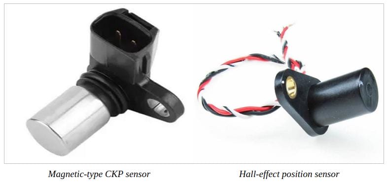
Inductive and Hall Effect CKP Sensors
Vehicles typically use one of 2 types of CKP sensors: inductive and hall-effect.
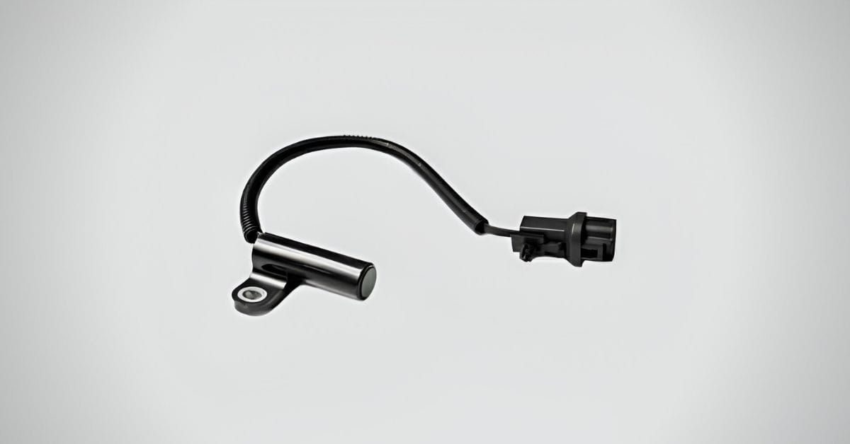
- An inductive (magnetic) CKP sensor has 1 or 2 wires (sometimes 3), is usually mounted before a rotor or relayer wheel, and produces its own AC voltage signal.
- A hall-effect CKP sensor has 3 or 4 wires, is mounted before a rotor or relayer wheel, generates a digital (square wave) signal, and relies on an external power source and ground to generate a signal.
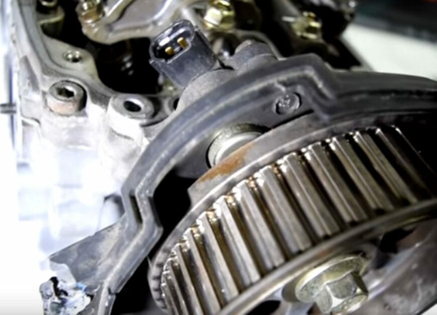
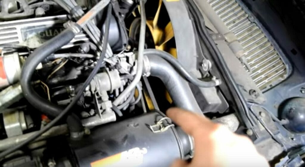
Locating the CKP Sensor
You can typically find the CKP sensor in one of the following locations, depending on your vehicle’s make and model:
- Near the crankshaft pulley
- Mounted on an engine front or timing cover
- Near the center of the engine block
- On the engine’s rear
- Behind the harmonic balancer
- Under the starter motor.
- At the transaxle’s bell housing, near the flywheel ring gear
Bad CKP Sensor Symptoms
A CKP sensor endures heat and vibration when an engine runs, which can eventually take a toll on it. A failed or bad CKP can cause one or more of the following symptoms:
- Difficult to start
- No-start situation with a cranked engine
- Starting and stalling condition
- Irregular stalling
- Rough idle time
- Hesitation
- Sluggish acceleration
- Increased fuel use
- Misfiring
- The check engine indicator light remains on
- The tachometer functions incorrectly or not at all
Malfunctions in other systems, such as the fuel or ignition systems, can cause some of the same symptoms. As a result, a crankshaft position sensor test is critical for a more accurate diagnosis. A multimeter can test your CKP regardless of whether it’s an inductive or hall effect sensor.
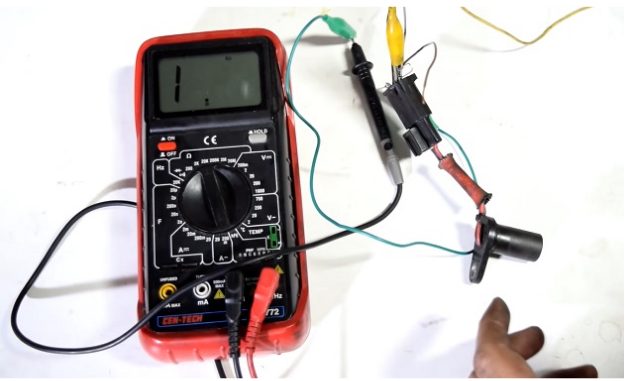
Testing a Crankshaft Position Sensor with a Multimeter
Many CKP problems can be in the wiring harness or the sensor’s connector.
Check them carefully before using a multimeter to test the sensor itself. Below are the steps to test a crankshaft position sensor with a multimeter. We will conduct one of the following pairs of tests, depending on which type of sensor you have:
- A voltage and resistance test on a 2-wire or inductive-type CKP sensor
- A voltage and duty cycle signal test on a 3-wire or hall effect type CKP sensor
Four tests are described below. If you have an inductive (or magnetic) type CKP sensor, you only need to do the first 2 tests, whereas the last 2 apply if you have a hall-effect type CKP sensor.
Testing a 2-Wire or Inductive Type CKP Sensor: Voltage Test
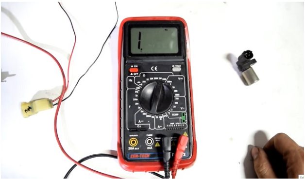
Step 1: Unplug the CKP Sensor
Unplug the electrical connector for the CKP sensor.
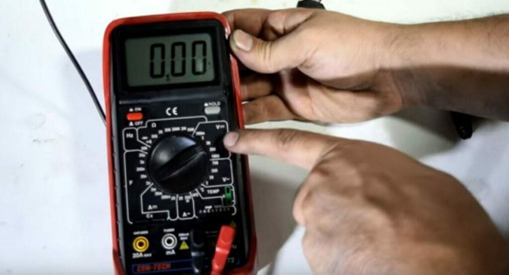
Step 2: Set the Multimeter
Set the digital multimeter to DC voltage settings using a low range.
Step 3: Turn the Ignition On
Toggle the ignition key to its “On” position without starting your engine.
Disable the fuel system by disconnecting the fuel pump fuse or relay to prevent the engine from starting. Alternatively, you can disconnect the ignition cable between the distributor and the ignition coil.
Step 4: Connect the Probes
Connect the multimeter’s probes as follows:
- Connect your multimeter’s black lead to the ground. It can be a clean engine surface, a metal bracket, or the battery’s negative (-) terminal, but it must be bare metal.
- Connect your multimeter’s red lead to each sensor wire on the disconnected harness connector.
Step 5: Interpret the Reading
A typical reading is between 0.3 and 1.5 volts.
If one of the cables produces below 0.3 or above 1.5 volts, the sensor is not receiving a proper reference voltage and must be repaired.
Step 6: AC Voltage Test (Optional)
Choose a low range on the AC voltage scale on your digital multimeter.
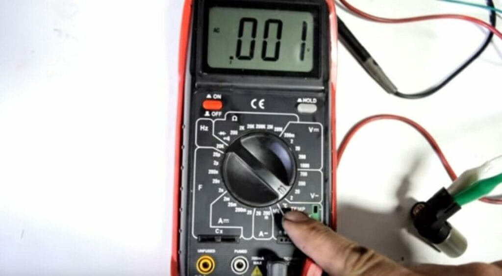
Connect the sensor pins to your multimeter’s leads.
During this test, ensure the lead wires are kept from moving engine parts. Also, have an assistant crank the engine briefly while watching the multimeter’s display.
Your sensor should generate a voltage-pulsing signal. Replace the sensor if no voltage pulses are visible. If your multimeter can detect frequency (Hz) measurements, you can also use this option to check for an AC signal.
Compare your results to the manufacturer’s specifications. I recommend consulting your vehicle’s repair manual for assistance.
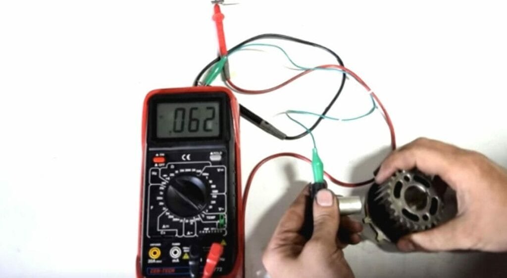
Testing a 2-Wire or Inductive Type CKP Sensor: Resistance Test
You can examine the resistance of your inductive CKP sensor by doing the following steps:
Step 1: Unplug the CKP Sensor
Unplug the CKP’s electrical connector.
Step 1: Set the Multimeter
Set your digital multimeter to measure ohms (resistance).
Step 3: Connect the Probes
Connect one multimeter lead to one of the sensor pins and the other to another pin.
Step 4: Interpret the Reading
Turn your multimeter on.
Depending on the model of your vehicle, the reading should show a resistance value of between 200 and 2000 ohms. Certain models may have lower upper limits (around 900 ohms).
Compare your results to the specs provided by the manufacturer. You can find it in your vehicle’s repair manual. Replace the sensor if it is not up to specification:
- If the result shows infinite resistance, the sensor has an opening in the circuit and needs replacing.
- If the result shows zero ohms, your sensor has a short circuit.
Testing a 3-Wire or Hall Effect Type CKP Sensor: Voltage Test
A Hall effect CKP sensor is best tested using an oscilloscope, but you can use a multimeter instead if you don’t have one.
Although you won’t get a graphical display for voltage and frequency (typically square wave signals), you’ll get an average voltage value from the sensor to give an idea of its effectiveness. However, unless stated in the vehicle’s repair manual, don’t check a Hall effect CKP sensor’s resistance, only the voltage. The induced voltage can damage internal components.
Step 1: Prevent the Engine from Starting
During this test, disconnecting the fuel pump fuse or relay prevents the engine from starting.
If the engine has a distributor, unplug the central ignition cable and use a jumper wire to connect it to the engine’s body for grounding.
Step 2: Unplug the CKP Sensor
Unplug the CKP’s electrical connector.
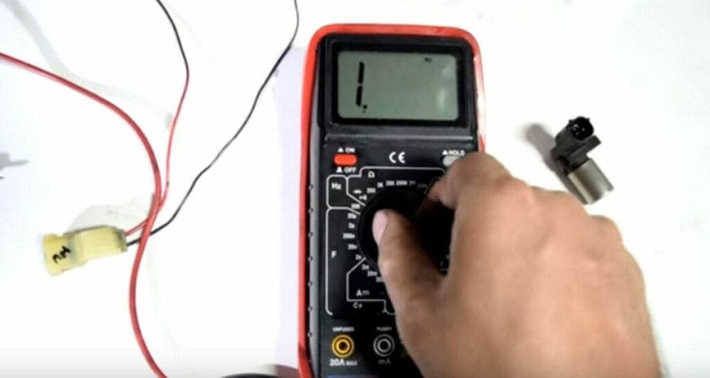
Step 3: Set the Multimeter
Set your digital multimeter to DC volts with a 20-volt range.
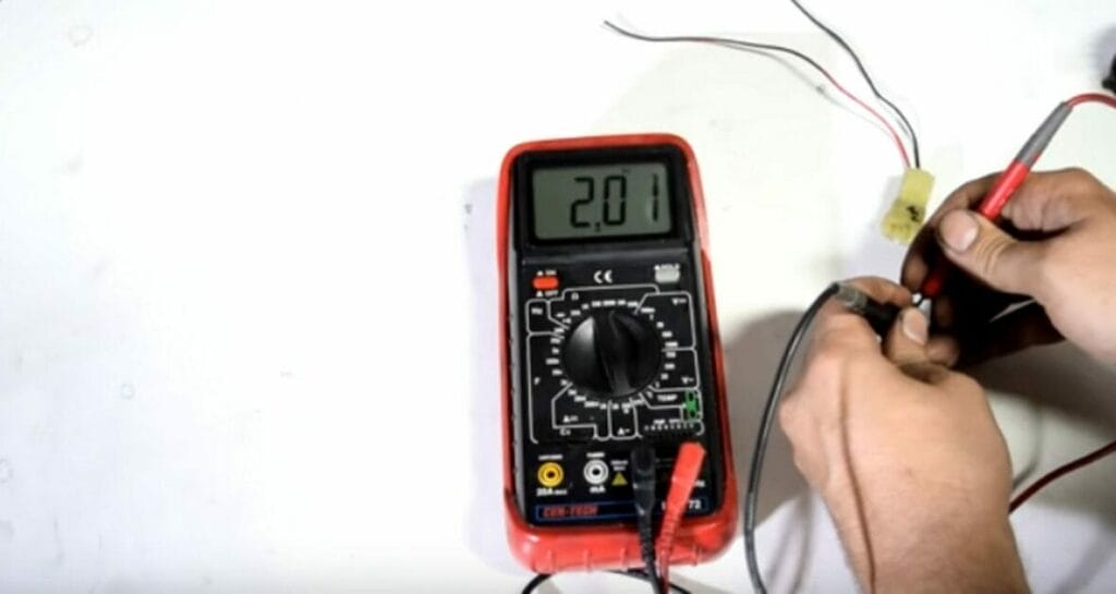
Step 4: Connect the Probes (Power Test)
Connect the multimeter’s probes to test the power as follows:
- Connect the black lead to the harness connector’s black wire.
- Connect the red lead to the harness connector’s red (power) wire.
If the CKP sensor uses various colored wires, you might need to check the wiring schematic for your specific model to distinguish the power, ground, and signal wires.
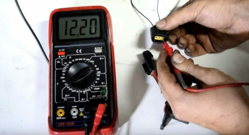
Step 5: Turn the Ignition On
Toggle the ignition key to the ‘on’ position without starting the engine.
Step 6: Obtain and Interpret the Reading
The reading should be between 5 and 12 volts, depending on the sensor used.
You can find the reference voltage value for your specific model in your vehicle’s repair manual. It’s typically 5, 7, or 12 volts.
Check the connector and wire for damage or a loose terminal connection if your reference voltage is less than expected, zero, or inconsistent. Also, examine the vehicle’s computer if necessary.
Step 7: Turn the Ignition Off
Turn off the ignition, then reconnect the CKP sensor to the harness connector.
Step 8: Set the Multimeter
Set your multimeter to read millivolts through a low DC voltage preset.
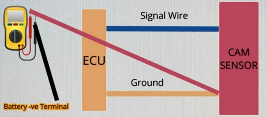
Step 9: Connect the Probes (Ground Test)
Connect the multimeter’s probes as follows:
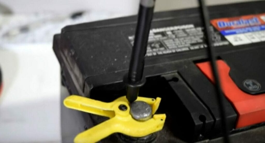
- Connect your multimeter’s black lead to the battery’s negative terminal.
- Connect the red lead to the sensor’s ground wire or pin.
Crank the engine for a short while. Have an assistant help you if necessary.
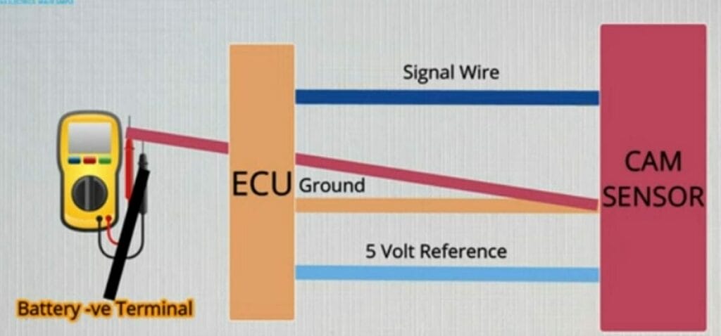
Step 10: Interpret the Reading
The multimeter should display around 200 mv to 300 mV.
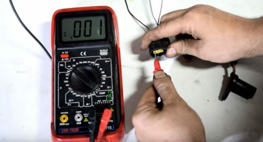
Step 11: Connect the Probes (Signal Test)
Connect your multimeter’s red lead to the green (signal) wire on the harness connection or CKP sensor.
Keep the black lead attached to the ground wire or the battery’s negative terminal. Then, crank the engine for a few seconds.
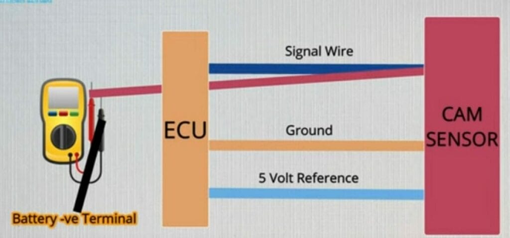
Step 12: Interpret the Reading
You should see around 300 mv on your multimeter’s display.
That is the average voltage value that a CKP sensor produces.
Testing Duty Cycle Signals on a 3-Wire Hall Effect Type CKP Sensor
Depending on your system, you can detect a CKP signal with your multimeter if it can read Duty Cycle signals.
You must back-probe the sensor’s signal wire and connect the multimeter’s black lead to the ground.
- Set the multimeter to Duty Cycle and have someone else start the engine.
- The sensor may be defective if the CKP fails to give a duty cycle signal.
Also, don’t check a Hall effect CKP sensor’s resistance unless specified in your car repair manual because the induced voltage can damage internal components.
FAQs
CKP Sensor: What Exactly Does It Do?
In general, the CKP monitors piston movement and the crankshaft’s position. It also assists the computer in keeping track of engine misfires and speed. With that data, the computer adjusts the ignition timing and fuel injection.
However, the crankshaft sensor is subjected to heat and vibration during engine operation. It wears on the sensor, or its circuit may eventually fail. A diagnostic trouble code (DTC) referring to a problem with the CKP sensor or the sensor’s circuit may be stored in the car’s computer, as it is with other emission-related sensors:
- P0315
- P0335-P0339
- P0385-P0389
You may also encounter the following code if your engine has a camshaft position (CMP) sensor:
- P0016-P0019
What are the two types of CKP sensors?
CKP sensors come in two varieties, which are used in the majority of automobiles nowadays:
- An Inductive (Magnetic) CKP Sensor has one or two wires and generates its AC voltage signal.
- A Hall-Effect CKP Sensor has three to four wires, produces a square wave digital signal, and needs an external power source and ground to make the signal.
Where is the CKP Sensor Located?
Depending on your vehicle’s make and model, you can find the CKP sensor in the following locations:
- In the front or timing cover of the engine, near the crankshaft pulley, or behind the harmonic balancer.
- Around the center of the engine block.
- Under your vehicle’s starter motor.
- On the back of the engine, near the flywheel ring gear, in the bell housing of the transaxle.
- If necessary, I recommend consulting your vehicle’s service manual to find the sensor for your model.
What if my CKP passes the test?
Even if your engine exhibits the symptoms of a faulty CKP, this does not always imply that your sensor, wiring, or connector is malfunctioning.
The issue may be caused by the components with which it communicates. Depending on your model’s specific design, there could be an issue with the ignition control module (ICM) or, less commonly, the PCM itself. Consult your owner’s handbook if necessary.
You could also check the camshaft position sensor to see if the ignition system produces a spark or the fuel injectors are not working.
References
Website Resources:
- fuel system. https://www.sciencedirect.com/topics/engineering/fuel-system
- coil. https://www.britannica.com/technology/coil
- Hall-effect CKP sensor. https://www.ampefi.com/product/hall-effect-crankshaft-position-sensor/
- Magnetic type CKP sensor. https://dir.indiamart.com/impcat/crank-sensor.html
Books:
- Erjavec, Jack & Rob Thompson. Automotive technology: A systems approach. 7th edition. Cengage. 2020. https://www.cengage.com/c/automotive-technology-7e-erjavec-thompson/9781337794213/
Video References:
Ratchets And Wrenches
Easy Car Electrics