7 min read
How to Test an ECU with a Multimeter (4–Step Guide)
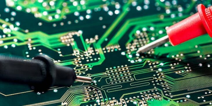
Your car can break down and stop for many different reasons, diagnosing these issues is essential to resolving them. The problem might well be in the ECU. But how do you check it?
To Test an ECU with a Multimeter, you need to follow 4 simple steps: 1. Setup the Multimeter, 2. Do a Visual Inspection, 3. Connect and follow our testing guidelines, 4. Record the Reading.
Confused? Don’t worry, I will go into more detail about this below.
How to Test an ECU with a Multimeter
Here are 4 simple steps that you need to follow when testing your ECU with a multimeter:
Step 1: Setup the Multimeter
A multimeter is composed of 3 main parts:
– The display
– The Selection knob
– The Ports
The display of the multimeter has four digits and the ability to display a negative sign.
The selector knob allows the user to set the multimeter to read different values such as amperage (mA), voltage (V), and resistance (Ω). We have to plug the two probes of the multimeter into the ports at the bottom of the display of the device. There are two probes, a black probe, and a red probe.
The color probe plugs into the Com port (short for Common), the red probe usually plugs into the mAVΩ port. This port can measure currents up to 200mA. Here V denotes voltage and Ω resistance. There is also a 10A port, which is a special port that can measure more than 200mA.
Getting Started
Next, we set up the multimeter to measure the current (mA). To be able to measure the current, we have to physically disconnect the current and put the meter in the line. The first step requires a piece of wire, we will physically break the circuit to measure the current. Unplug the VCC wire going to the resistor, add one to where it’s connected, then probe from the power pin on the power supply to the resistor. This effectively shuts off the power to the circuit. In the second step, we’ll put the multimeter in line so that it can measure the current as it flows through the multimeter into the circuit board.
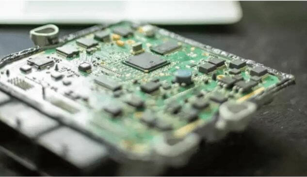
Step 2: Visual Inspection
When inspecting directly, we need to make notes. First, we need to check the ECU is working properly or not. We should look outside to see if the ECU is cracked, or badly damaged.
Attention: Please observe from both sides because just a small crack or signs of scorching can mean that the ECU is faulty, or inoperable. If damaged, the meter will be checked to see if it is connected to the ECU and that the test leads are properly connected to the port. After observing everything we can start taking multimeter measurements.
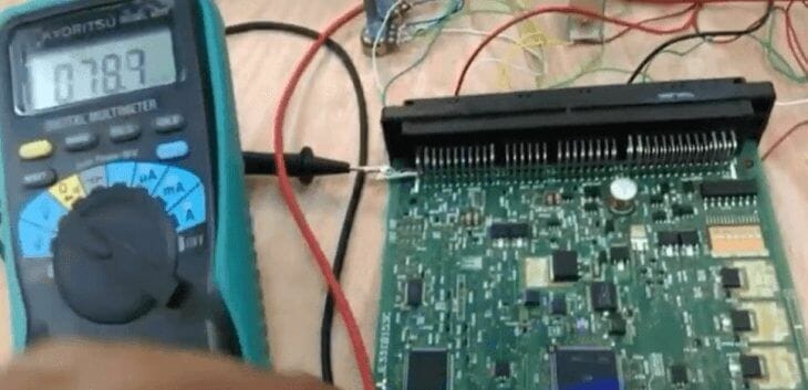
Step 3: Start Testing with A Multimeter
You need to test each component using your digital Multimeter. You should start by testing the fuse and relay first and then perform the amperage draw. A test needs to be done to make sure that there is enough power going to the engine computer and also test the voltage going through the sensor and the fuses. Make sure there is power to the components when conducting the test. (1)
The testing process includes the following steps:
- Leave the current on the A scale to measure AC.
- Black test leads to COM port, red test leads to mAVΩ port.
- Set switching of multimeter clock at scale A-250mA.
- Turn off the power of the test circuit.
- Connect the red probe in the direction of the (+) pole and the black probe in the (-) direction in the direction of the current in the experiment. Connect the meter to the test circuit.
- Power on the test circuit.
These are the steps to conduct an ECU test with a multimeter. Pay attention to the index scales to get the best results for the test.
Step 4: Record the Reading
After conducting the ECU test, we will see the results appear on the multimeter screen. For a digital multimeter, the result is easy to read. For analog, I will tell you the steps to read the measurement results.
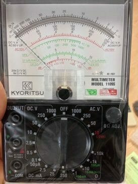
- Determine the correct scale on the multimeter. The multimeter has a hand located behind the glass, which moves to point to the result. Usually, there will be three arcs printed on the background behind the needle.
The Ω scale is used to measure resistance and is usually the largest arc at the top. On this scale, the value 0 is to the right instead of the left like on other scales.
– The “DC” scale indicates the DC voltage reading.
– The “AC” scale indicates the AC voltage reading.
– The “dB” scale is the least used. You can see a short description of the “dB” scale at the end of this section.
- Write the voltage scale index. Look closely at the DC or AC voltage scale. There will be several rows of numbers below the scale. Check the range you selected on the knob and look for the corresponding symbol next to one of these rows. This is the row of numbers from which you will read the result.
- Estimated value. The voltage scale on an analog multimeter works similarly to a regular gauge. The resistance scale is built based on the logarithmic system, which means that the same distance will show different changes in value depending on the position the needle is pointing at. (2)
After completing the steps, we will get the measurement result. If the measurement result exceeds 1.2 amps, the EUC is faulty, if the result is less than 1.2 amps, the ECU works normally.
Note: When performing an ECU test, the ignition must always be off for maximum testing effectiveness.
Caution for Testing an ECU with a Multimeter
There are a few things that you should beware of when you want to test ECU with a Multimeter. These cautions will safeguard both your safety and the safety of the engine control unit and they are as follows:
Gloves
When you plan to use a meter to test the ECU, the first thing you should do is put on hand gloves.
Examine Visually
It’s vital to have a look around the engine control unit and make sure everything is in working order.
Check the Multimeter
To get an accurate test of your engine control unit, make sure your multimeter is working properly and is properly powered.
Ignition Key
When using a multimeter to test the ECU, make sure the ignition key is turned off.
ECU Connection
When the engine is turned on, do not unplug the engine control units. Pay attention when connecting the ECU terminal.
Wrapping Up
Practicing measuring the ECU with a multimeter is a complicated and time-consuming process for the novice or the inexperienced. This article will help you to solve this problem. The above-mentioned steps are the most important details that you should pay attention to during the practice of testing the ECU with a multimeter.
Before you go, we’ve listed a few multimeter testing guides below. You may want to check them or bookmark them for later reading. Until our next learning guide!
- How to Test Ignition Control Module with Multimeter
- How to Read an Analog Multimeter
- How to Test a Capacitor with a Multimeter
References
(1) computer – https://www.britannica.com/technology/computer
(2) logarithmic system – https://study.com/academy/lesson/how-to-solve-systems-of-logarithmic-equations.html
Video Reference