7 min read
3 Wire Crank Position Sensor Wiring Diagram
In this article, you’ll learn about the 3-wire crank position sensor and its wiring diagram.
If you ever had to install or test a 3-wire crankshaft sensor by yourself, you probably know the drill. Identifying the 3-wires won’t be an easy task. On the other hand, you should know where to connect them.
The crankshaft sensor is an important electrical device to detect engine RPM and ignition timing. The 3-wire crank sensor comes with a 5V or 12V reference, signal, and ground terminals. These three terminals connect to the vehicle’s ECU.
“Note: Depending on the model of the vehicle, the crank sensor’s wiring diagram might vary.”
Learn everything about 3-wire crank sensors from the below article.
Need to Know Things About Crankshaft Sensor
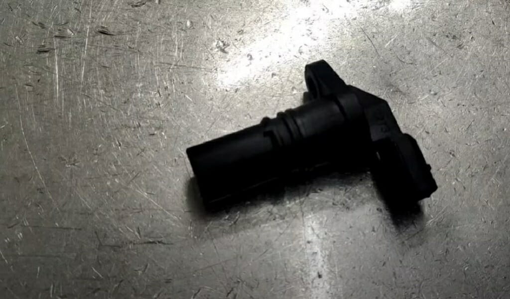
The primary duties of a crankshaft sensor are detecting engine RPM and ignition timing. This sensor is a vital part of both diesel and petrol engines.
Note: Depending on the model of the vehicle, the crank sensor’s wiring diagram might vary.
For instance, some models come with a 2-wire sensor, and some come with a 3-wire sensor. Either way, the working mechanism and wiring diagram won’t differ much.
Quick Tip: 3-wire crank sensor can be categorized as a hall-effect type sensor. It includes a magnet, transistor, and steel material such as germanium.
Wiring Diagram for 3 Wire Crankshaft Sensor
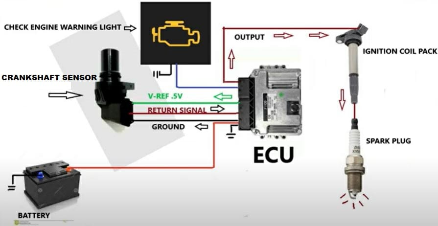
As you see from the above diagram, a 3-wire crankshaft sensor comes with three wires.
- Reference voltage wire
- Signal wire
- Ground
All three wires connect to the ECU. One wire receives the power from the ECU. This wire is known as a reference voltage wire with a voltage of 5V (or 12V).
The signal wire goes from the sensor to the ECU. And lastly, the ground wire comes from the ECU, like the 5V reference wire.
Reference Voltage and Signal Voltage
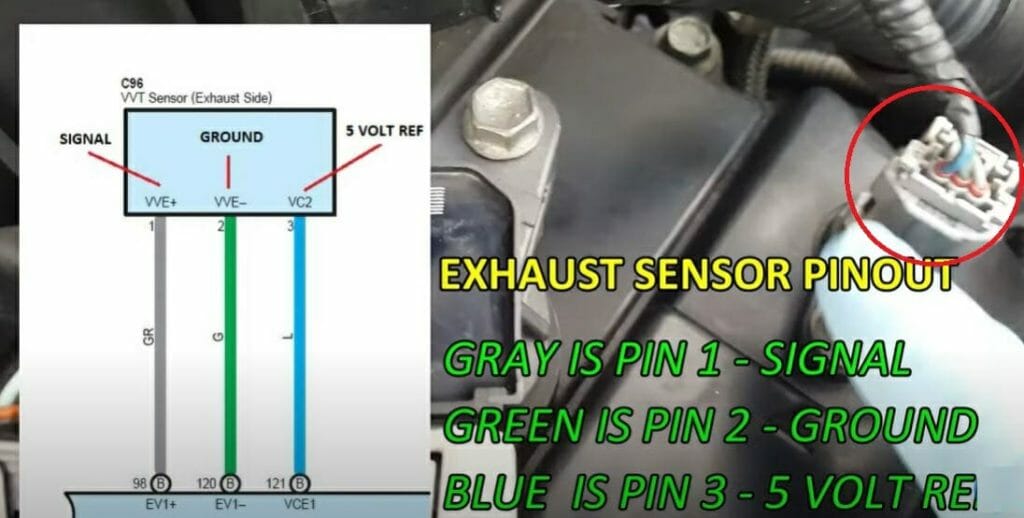
To understand the wiring diagram properly, you’ll need a better idea of the reference and signal voltages.
The reference voltage is the voltage that comes from the ECU to the sensor. Most of the time, this reference voltage is 5V, and sometimes, it might be 12V.
The signal voltage is the voltage that goes to the ECU from the sensor.
Quick Tip: Checking your vehicle’s manual is the best method to identify the crankshaft sensor type. For instance, the manual has details such as sensor type and voltage.
How Does the 3-Wire Sensor Work?

When an object comes near the sensor, the sensor’s magnetic flux changes, leading to voltage production. Finally, the transistor amplifies this voltage and sends it to the car computer.
Difference Between The 2 Wire and 3 Wire Sensors
The 3-wire sensor has three connections with the ECU. And the 2-wire sensor only has two connections. It has signal and ground wires, with no reference wire for the 2-wire crank position sensor. The signal wire sends the voltage to the ECU, and the ground wire completes the circuit.
Three Types of Crank Sensors
There are three types of crankshaft sensors. In this section, I’ll give a brief explanation of them.
Inductive
Inductive sensors use a magnet to pick up engine cracking signals. These types of sensors are mounted on the engine block, and you’ll be able to locate the crankshaft sensor close to the crankshaft or the flywheel.
The inductive-type sensors don’t need any reference voltage; they produce their own voltage. Hence, the 2-wire sensor is an inductive type crankshaft sensor.
Hall Effect Sensor
The hall effect sensors are located in the same place as the inductive sensors. However, these sensors need power from an outside source to operate. Hence, they come with a reference voltage wire. As I mentioned, this reference voltage can be 5V or 12V. These sensors create a digital signal from the received AC signal.
Quick Tip: The 3-wire crank sensors are the hall effect sensor type.
AC Output Sensors
AC output sensors are a bit different from the others. Instead of sending digital signals like in the hall effect sensors, AC output sensors send an AC voltage signal. These types of sensors are commonly used in Vauxhall EVOTEC engines.
FAQs
How Many Wires Connect to the Crankshaft Position Sensor?
The number of wires might vary depending on the vehicle model. For instance, some vehicle models come with 2-wire sensors, and some come with 3-wire sensors.
As you can imagine, a 2-wire sensor has two wires, and a 3-wire sensor has three wires.
Why Should the 3 Wire Crankshaft Sensors Need a Reference Voltage?
The 3-wire crankshaft sensors need voltage from an outside source to create the signal voltage. Hence, these sensors come with three terminals, and one of them represents the reference voltage. The other two terminals are for signal and ground connections.
However, 2-wire crankshaft sensors don’t need any reference voltage. They produce their own voltage and use it to create the signal voltage.
Is the Reference Voltage 5V for Every Crankshaft Sensor?
No, the reference voltage won’t be 5V every time. Some crank sensors come with a 12V reference voltage. But remember, the 5V reference voltage is the most common one.
Why is 5V Reference Voltage Common in the Automobile Industry?
Even though the vehicle batteries produce 12.3V to 12.6V, the sensors use only 5V as their reference voltage.
Why cannot sensors use the whole 12V?
Well, it is a little complicated. For instance, when you start the vehicle, the alternator kicks in and produces a little more voltage in the 12.3V to 12.6V range.
But the voltage that comes out of the alternator is highly unpredictable. It might release 12V a sometimes it might release 11.5V. So, producing 12V crankshaft sensors is risky. Instead, manufacturers produce 5V sensors and stabilize the voltage using a voltage regulator.
Can I Test the Crankshaft Position Sensor?
Yes, you can test it. You can use a digital multimeter for this. Check the sensor’s resistance and compare it with the rated resistance value. If you get a big difference between these two values, the crankshaft sensor is not working properly.
Take a look at some of our related articles below.
- 3-pin horn relay wiring diagram
- What do spark plug wires connect to
- How to hook up 2-amps with 1 power wire
Video References
mechanic brother
Chef Truck Mechanic
JLS Etnuper
Car-Parts2.0