11 min read
How to Splice the Wires for a Security Camera (Steps & Guide)
Splicing will be necessary if your security camera cable is too short or damaged.
You could replace the entire cable with a longer one, but if splicing (joining two cables) is right for you, I’ll show you how to do it. I’ve covered both types of cables used by security cameras.
The easiest way to splice security camera cables, which are Siamese coaxial for analog cameras or Ethernet for digital ones, is to use a coupler. Otherwise, splice them by joining the same color or type of wires and twisting, soldering, crimping, taping, or heat shrinking them.
Follow this guide’s detailed and illustrated steps to splice either type (Siamese coaxial or Ethernet).
Splicing Security Camera Wires
Why Splice Wires?
You may need to splice wires when extending a cable to make it reach where you want it to or if joining a broken one.
The splice must be good because it can affect the picture quality.
Types of Wires
I will show how to splice two types of wires security cameras use: Siamese coaxial and Ethernet (Cat 5/6). See the section at the end on ‘Security Camera Wires’ for more information about them.
Requirements
You will need the following items for splicing the two different types of security camera wires:
- Cables: RG59 or similar for analog or Cat 5/5e/6 for digital
- Cable connectors: coaxial cable connectors (male and female) for analog and RJ45 ones for digital
- Tools: wirecutter, wire stripper, wire crimper, and a heat gun
- Instruments: cable tester
- Materials: heat shrink tube, electrical tape
Procedure for Splicing Security Camera Wires
Follow these steps first for splicing security camera wires irrespective of the type of wire:
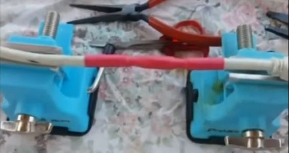
Using a Coupler
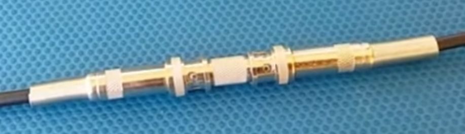
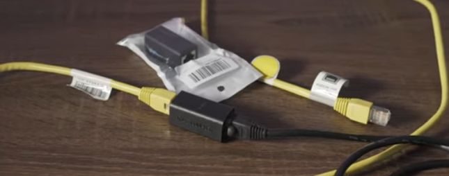
Using a coupler is an alternative to splicing, which you may find easier and quicker.
However, it’s only possible if both ends to be joined have connectors on them. Obtain a compatible coupler, insert both ends and wrap electrical tape around it to secure the connection.
So, you should still learn to apply the splicing method if you splice wires without connectors or because a coupler is unavailable.
Splicing Wires Without Connectors
Follow one of the two methods below to splice wires without connectors (or if you can’t obtain a coupler) according to the cable type (Siamese coaxial or Ethernet).
What Splicing Involves
Splicing involves joining two or more bare wire ends together by spirally twisting, soldering, attaching an insulated connector, or using a crimp terminal.
First, strip 1/2-1″ of the insulation off their ends. If twisting, do so in a clockwise direction using pliers. Then, apply the method as instructed for securing the joint.
Splicing a Siamese Coaxial Cable (12 Steps)
Step 1: Strip the Cables and Wires
Cut the two cables as necessary and strip their outer insulation and all the wires using a wire stripper. Stripping about half an inch will do.
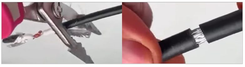
Step 2: Attach a Heat Shrink Tube
Place a heat shrink tube over one of the two cables.
Step 3: Pull the Mesh Back
Pull back the braided mesh of both cables.
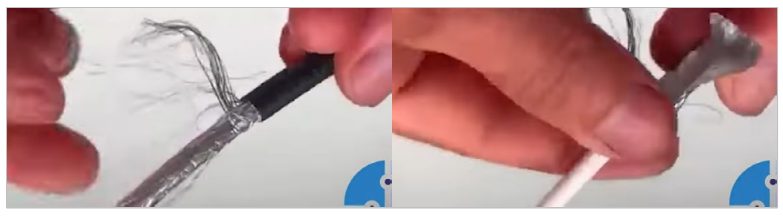
Step 4: Strip the Shielding
Cut and strip back the shielding and the additional insulation layer as necessary. Be careful not to cut too deeply. Repeat this for the other cable.

Step 5: Add Another Heat Shrink Tube
Add another heat shrink tube over one of the cables.
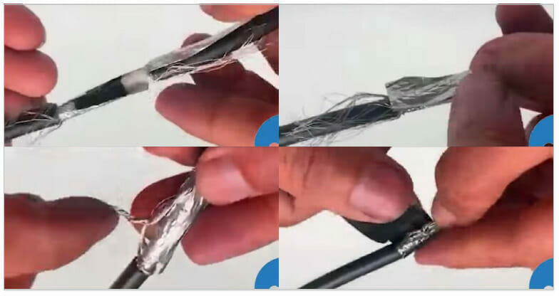
Step 6: Crimp the Wires
Join the cores of each cable by twisting or combining them using a butt crimp.

Step 7: Tape the Wires
Tape the core wires using electrical tape (see the picture above on the right in Step 6).
Step 8: Tighten the Heat Shrink Tube
Move the second heat shrink to cover the ends of both cables to cover them roughly equally. Then, use a heat gun to shrink it and secure all the joints.
Step 9: Crimp the Mesh
Connect the two braided meshes of both cables or crimp them together.
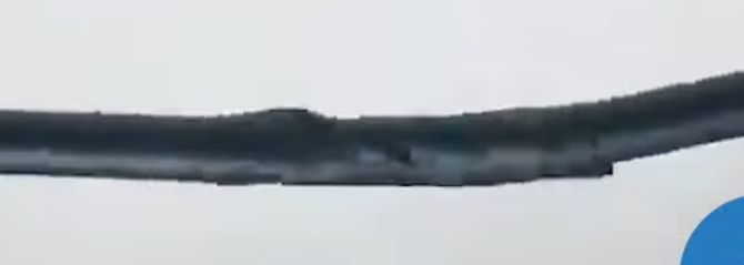
Step 10: Tighten the Heat Shrink Tube
Move the first heat shrink to cover both braided meshes roughly equally. Then, use a heat gun to shrink it and secure the joint.
Step 11: Tape the Cables
Wrap electrical tape around the joint of both cables.
Step 12: Repeat the Process
Repeat the above process for any additional wires, as some have them for sound and tilting features.
Step 13: Attach the Connectors
Finally, attach the right connectors at the other ends that will be plugged in.
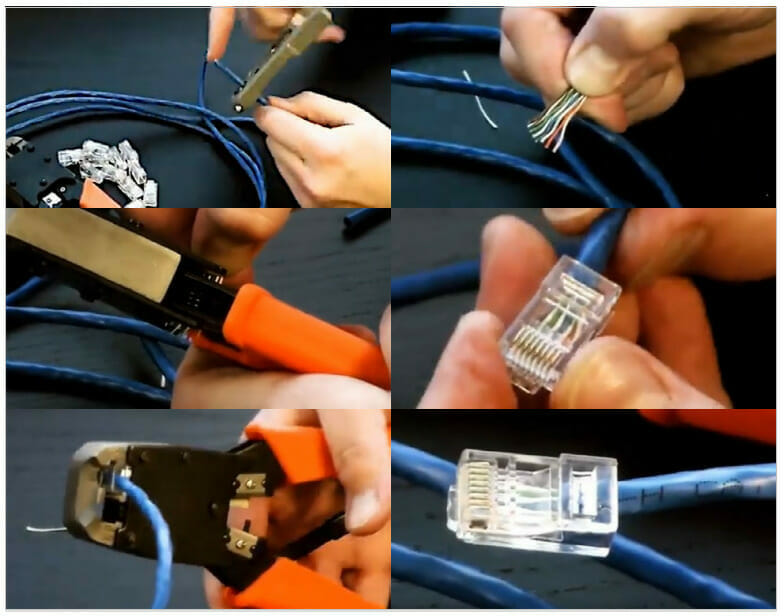
Splicing an Ethernet Cable (6 Steps)
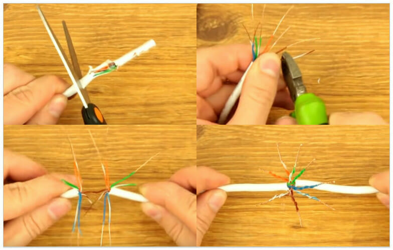
Step 1: Strip the Cables and Wires
Cut the two cables as necessary and strip their outer insulation and all the wires using a wire stripper. Stripping about half an inch will do. You may need to open the twists of all the pairs if they are twisted.
Step 2: Attach a Heat Shrink Tube
Place a heat shrink tube over one of the two cables.
Step 3: Crimp the Wires
Use a butt crimp to combine each of the 8 internal wires together. Remember to join only like wires together, i.e., of the same color.
Step 4: Tape the Wires
Tape the 8 wires individually using electrical tape.
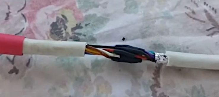
Optionally, wrap the whole joint with electrical tape if you won’t use a heat shrink tube.
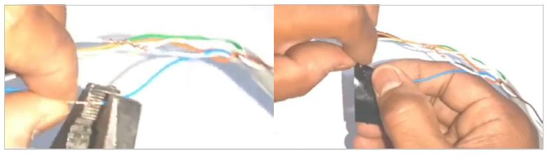
Step 5: Test the Connection
Attach an RJ45 connector at one or both of the other two (non-joining) ends as required. Then, test the connection before sealing the cable for good.
If unsure, use the chart below to know which wire goes where.

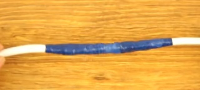
Step 6: Tighten the Heat Shrink Tube
Move the heat shrink to cover the ends of both cables to cover them roughly equally. Then, use a heat gun to shrink it and secure all the joints.
More About Security Camera Wires
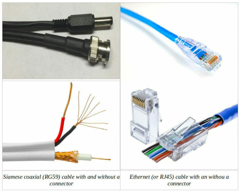
Security cameras normally use either of two main types of wires:
- Siamese coax (e.g., F-type, BNC, or RG59) cables are used by analog and HD-TVI security cameras;
- Ethernet (e.g., cat5, cat5e, or cat6 with RJ45 connectors) cables are used by digital security cameras.
Traditional, non-digital (analog) cameras use regular 3-wire shielded cables, as used by analog TVs. The shielding allows them to be used over longer distances than is possible with Ethernet cables. Audio-capable analog cameras require an additional wire in the cable to support audio signals.
An analog security camera system is usually cheaper than a digital one and doesn’t require network access.
Digital security cameras, called IP cameras, use Ethernet (Cat 5/6) cables with RJ45 connectors. The Ethernet cables provide network access. Some PoE-enabled IP cameras also receive power through them.
Ethernet cables contain 8 insulated copper wires split into 4 pairs, where the 2 wires in each pair are twisted around each other. They are also called “twisted pair” cables.
References
Website Resources:
- Ethernet cable with a connector. https://readytogocables.com/what-is-rj45-wires-and-what-are-its-uses/
- Ethernet cable without a connector. https://www.dintek.com.tw/index.php/Articles/Using-dintek-s-rj45-plugs-to-get-connected.html
- Siamese coaxial cable with a connector. https://av-cables.net/plenum-siamese-rg59-u-bnc-coaxial-cable-with-18-2-power-cable/
- Siamese coaxial cable without a connector. https://www.amazon.com/Plenum-Siamese-Coaxial-Power-Conductor/dp/B0082K86E2
Video References:
Cable Splicer
Caramba Hacks
Greatest Unknown
HardwareSense
Mr Technic
Pearl Engineering
Pinoy TechCentral
Priyo Tech & Reviews