7 min read
How to Find a Short Circuit with a Multimeter (6-Step Guide)
Have you encountered a short circuit issue while working on your electrical circuits or devices? When a short circuit permanently damages your electrical circuit or circuit board, this becomes an even bigger problem. Locating and eliminating a short circuit is critical.
In general, you can find a short circuit with a multimeter by following these steps:
- Determine the circuit component’s location
- Probe the circuit
- Examine the multimeter’s display
While there are different ways to find a short circuit, using a multimeter is one of the most straightforward. As a result, we’ve made this comprehensive explanation of how to find a short circuit with a multimeter.
What is a Short Circuit?
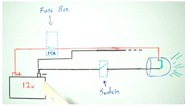
A short is a sign of a break or fray in the wire that causes an electrical system to malfunction. It is formed when a current-carrying wire comes into contact with a neutral or ground in a circuit.
Also, it could be an indicator of a short circuit if you see fuses blowing regularly or if a circuit breaker trips frequently. When the circuit is triggered, you may also hear loud popping sounds.
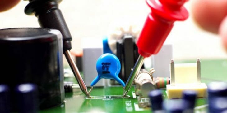
A multimeter is one of the primary tools that you can use to check for short circuits in your home’s wiring. You can check for electrical issues such as a short to the ground with it. A multimeter can even check for short circuits on a circuit board, such as on a desktop computer. Moreover, it can also check for a short circuit in your car’s electrical wiring.
Steps to Find a Short Circuit with a Digital Multimeter
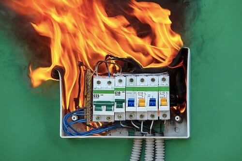
By resolving the electrical short circuit as quickly as possible, you’ll limit the risk of wire and insulation deterioration and prevent the circuit breaker from creating a fire. (1, 2)
To find a short circuit using a multimeter, follow these steps:
Step #1: Ensure Safety and Get Ready
It is critical to ensure that everything is done safely before using a multimeter to identify a short circuit. It guarantees that neither your electrical circuit nor your multimeter is harmed during the search for a short circuit.
Before examining anything, make sure that your electrical circuit is turned off. That includes removing the batteries and power adapters.
Note: If you don’t turn off all electrical power to a circuit before testing it, you could get a severe shock or electrocution. Hence, double-check that the circuit’s electricity is off.
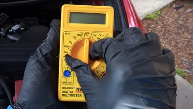
Step #2: Turn the Multimeter On and Set it Up
Turn on your multimeter after you’ve double-checked that everything is safe to use. Then, set it to either continuity test or resistance mode with the selector knob, depending on your multimeter’s capabilities.
Tip: If your multimeter has different resistance settings, it’s a good idea to select the lowest resistance scale.
Step #3: Test and Adjust the Multimeter
To guarantee that your multimeter provides you with all necessary measurements, you should test and calibrate it before using it. To do it, make a connection between the probe tips of your multimeter.
If it’s in resistance mode, the resistance reading on your multimeter should be 0 or almost zero. If your multimeter is giving you a reading that is much higher than zero, calibrate it such that when the two probes are touched together, the value is zero. On the other hand, if it’s in continuity mode, a light will flash, or a tone will sound, and the reading will be 0 or almost zero.
Step #4: Determine the Circuit Component’s Location
After setting up and calibrating your multimeter, you’ll need to locate and identify the components of your electrical circuit that you’ll be testing for short circuits.
That component’s electrical resistance should most likely not be zero. For example, the input of the audio amplifier in your living room next to your TV will almost certainly have a resistance of a few hundred ohms (at a minimum).
Bonus: Ensure that each component has at least some resistance when selecting these components, or else identifying a short circuit will be difficult.
Step #5: Probe the Circuit
After finding that component you will be checking for a short circuit, connect your multimeter’s red and black probes to the circuit.
For the metal tip of the black probe, you should connect it to the ground or chassis of the electrical circuit.
Then, connect the metal tip of the red probe to the component being tested or the section you believe has a short circuit. Ensure that both probes are in contact with a metal component, such as a wire, a component lead, or the circuit board foil.
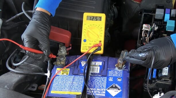
Step #6: Examine the Multimeter’s Display
Finally, pay attention to the readings on the multimeter display when you press the red and black probes against the metal parts of the circuit.
- Resistance Mode – if the resistance is low and the reading is zero or close to zero, the test current flows through, and the circuit is continuous. However, if a short circuit exists, the multimeter display will read 1 or OL (open loop), indicating a lack of continuity and an electrical short circuit in the device or circuit you’re measuring.
- Continuity Mode – the multimeter displays a zero value or nearly zero and emits a tone to signify continuity. However, there is a lack of continuity if the multimeter shows a reading of 1 or OL (open loop) and does not beep or make a tone. Lack of continuity indicates an electrical short circuit in the device you’re checking.
Tips on Using a Digital Multimeter to Find a Short Circuit
A multimeter may be used to examine short circuits and the performance of your circuit because it can function as a voltmeter, ohmmeter, and ammeter.
Select the Correct Device
To check for short circuits in an electrical circuit, make sure you’re using the proper type of multimeter. While all multimeters can measure current, voltage, and resistance, higher-end multimeters may perform various other tasks. For a more versatile multimeter, this could have additional readings, attachments, and modes.
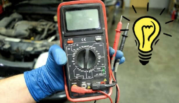
Get to know the Features and Parts
A vast display, a select knob, ports, and probes are the main components of your multimeter. However, earlier analog multimeters include a scale and a pointer instead of a digital display. The ports can be up to four in number, with half of them being red and the other half being black. The black port is for the COM port, while the other three are for readings and measurements.
Recognize Your Device’s Ports
While the black port is used for COM connection, the other red ports have various functions. The following ports are included:
- VΩ – a unit of measurement for resistance, voltage, and continuity test.
- µAmA – a unit of measurement for current in a circuit.
- 10A – used to measure currents of 200mA or greater.
Other multimeter’s learning and product guides which you can check are listed below;
- How to test a circuit breaker with a multimeter
- How to identify neutral wire with multimeter
- Best Multimeter
References
(1) insulation – https://www.energy.gov/energysaver/types-insulation
(2) creating a fire – https://www.rei.com/learn/expert-advice/campfire-basics.html