4 min read
How to Check a 3-Wire RTD with a Multimeter (5 Steps)
This article will show you how to check a 3-wire RTD with a multimeter.
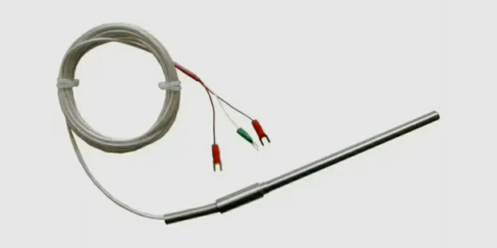
RTDs (Resistor Temperature Detectors) are sensors used to measure temperature. If you suspect the temperature is not being detected properly, you will have to test the RTD using a multimeter.
The test requires checking the resistance across the three wires and comparing the readings. In turn, the resistance across the white wire and each of the two red wires should be roughly the same, the exact value depending on the temperature. But the resistance across the same colored wires should be very low or close to zero. If this is the case, then the RTD is working properly.
The 3-Wire RTD
RTDs are available in 2-, 3-, and 4-wire configurations.
The 3-wire configuration provides a balance between the greater accuracy of the 4-wire configuration and the low cost of the 2-wire configuration. Furthermore, the 3-wire type can be used over a wide temperature range and with long lead wires to make more substantial readings. The 3-wire RTD is thus the preferred type.
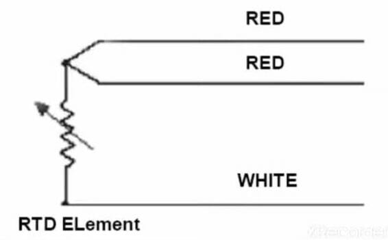
In the 3-wire RTD, the third wire computes the average resistance of the lead wire in the circuit to control the sensor measurement. It is subtracted from the read value for correction to allow for the effect of its resistance on temperature, thereby giving greater accuracy and effectiveness.
The 3-wire RTD has become the industry standard. It is used in various industrial contexts and processes, especially where monitoring and controlling temperature is critical.
Below is the wiring diagram for a 3-wire RTD.
Checking a 3-Wire RTD with a Multimeter
Step 1: Setup the Multimeter
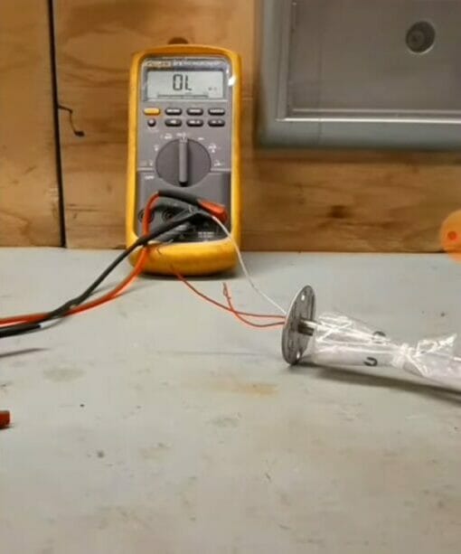
To check a 3-wire RTD with a multimeter, set it to read in ohms. The initial display should read ‘OL.’
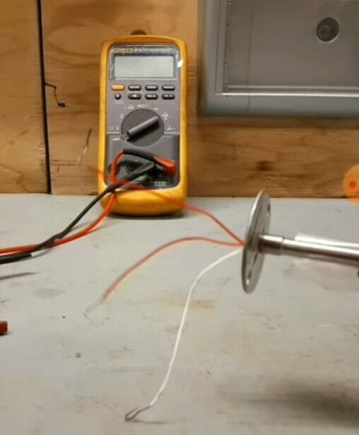
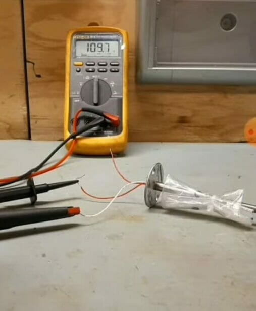
Step 2: Check the White Wire First
Use the multimeter to check the 3-wire RTD. Refer to the MFG for the wiring and color code. Here (see the picture below), it has been connected first to the white wire and the other probe to another wire. Take note of the reading, which is close to 110 ohms.
Step 3: Check the Colored Wire
Now connect the second probe to the other (third) lead. In this case, it is showing as 109.1 ohms.
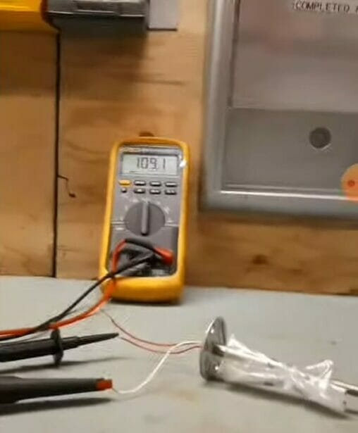
Step 4: Compare the Readings
The two values should be more or less the same. They are roughly the same in this case, with a difference of only 0.6 ohms (109.7 – 109.1). This corresponds roughly to around 75.2°F (24°C).
Step 5: Check across the Same Colored Wires
Now check across the same colored wires (with the white now excluded). The reading should show a very low resistance this time. Here, it is showing as 0.4 ohms.
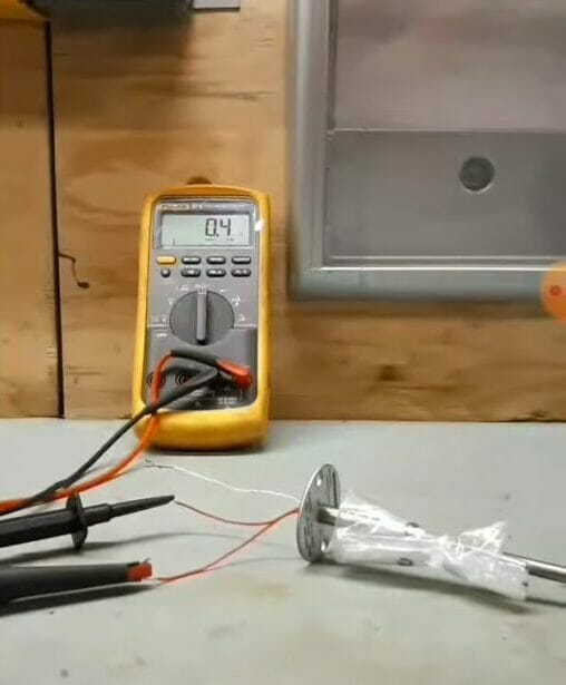
If the resistance is now lower, it indicates that the RTD is working correctly. If it isn’t, then the RTD may need replacing, but you can repeat the checking process to make sure.
Checking across the Node and Element
Also, check across the node and element using the hook lead.
The reading should be close to zero or one. The reading should be between 115 and 209 ohms if you center at room temperature.
Checking a 3-Wire RTD 830
If you’re checking a 3-wire RTD 830, it will have a connector with a red dot, indicating that it is the positive end. Use the jump lead to measure across its node, then jump over to its element. The reading should be approximately 109 ohms. If it is, then it indicates that your RTD is working properly.
Video Reference
Instrumentation and Control