5 min read
4 Wire Ignition Coil Diagram (Full Guide)
This article will provide some need-to-know information about the 4-wire ignition coil diagram.
The ignition coil is the heart of the ignition system, and improper ignition coil wiring can cause wrong electronic ignition, leading to cylinder misfires. So, you should be able to identify the 4-pins correctly when you use a 4-wire ignition coil. In this short article, I’ll teach you everything I know about a 4-wire ignition coil diagram and its working principle.
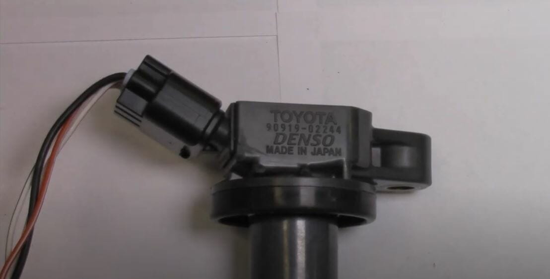
An ignition coil can produce very high voltages (around 50000V) using the battery’s 12V voltage. A 4-wire ignition coil comes with four pins; 12V, IGF, 5V IGT, and Ground.
I’ll cover more about this electronic ignition process in the below article.
What Does Ignition Coil Do?
An ignition coil converts low 12V voltage into higher voltages. Depending on the quality of the two windings, this voltage can get up to 50000V. This voltage is then used to produce the spark needed for the engine’s fuel combustion process (with the spark plugs). So, you can label the ignition coil as a short step-up transformer.
Quick Tip: Some mechanics use the term spark coil for ignition coil.
4 Wire Ignition Coil Diagram
When it comes to ignition coils, they come in many variations. For instance, you can find 2-wire, 3-wire, or 4-wire ignition coils in different vehicle models. In this article, I’ll talk about the 4-wire ignition coil. So, why is a 4-wire ignition coil so special? Let’s find out.
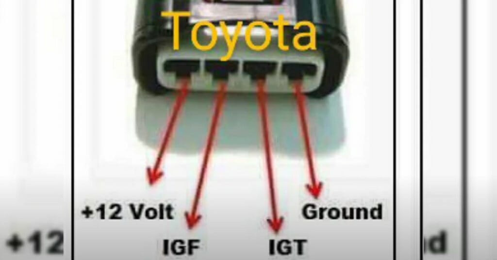
For starters, a 4-wire ignition coil comes with four pins. Examine the above image for the coil pack wiring diagram.
- 12V pin
- 5V IGT pin (Reference voltage)
- IGF pin
- Ground pin
12V pin comes from the ignition switch. The battery sends a 12V signal to the ignition coil through the ignition switch.
5V IGT pin act as the reference voltage for the 4-wire ignition coil. This pin connects with the ECU, and the ECU sends a 5V trigger signal to the ignition coil through this pin. When the ignition coil receives this trigger signal, it fires up the coil.
Quick Tip: This 5V reference voltage is useful for testing ignition coils.
IGF pin sends a signal to the ECU. This signal is a confirmation of a properly working ignition coil. The ECU only continues to operate after receiving this signal. When the ECU does not detect the IGF signal, it sends code 14 and stops the engine.
The ground pin connects to any ground point in your vehicle.
Working Principal of 4 Wire Ignition Coil
A 4-wire ignition coil has three main parts; the iron core, the primary winding, and the secondary winding.
Primary Winding
The primary winding is made from a thick copper wire with 200 to 300 turns.
The Secondary Winding
The secondary winding is also made from a thick copper wire, with around 21000 turns.
Iron Core
Made with a laminated iron core and is capable of storing energy in the form of a magnetic field.
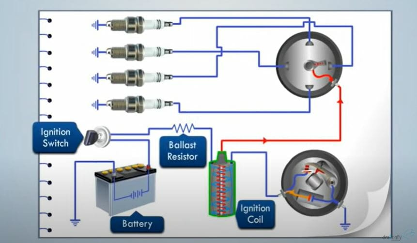
And here’s how these three parts generate around 50000V.
- When the current goes through the primary winding, it creates a magnetic field around the iron core.
- Because of the above process, the connection of the contact breaker gets disconnected. And collapse the magnetic field too.
- This sudden disconnection creates a very high voltage (around 50000V) in the secondary winding.
- Finally, this high voltage is transferred to the spark plugs using the ignition distributor.
How to Know a Vehicle Has a Bad Ignition Coil?
A bad ignition coil will cause all sorts of problems for your vehicle. For instance, the engine can start to misfire when accelerating the vehicle. And the vehicle might shut down suddenly due to this misfire.
Quick Tip: Misfire can happen when one or more cylinders fires incorrectly. Sometimes the cylinders might not fire at all. You might have to do an ignition coil module testing when that happens.
Apart from the engine misfire, here are some more signs for identifying a bad ignition coil.
- Check engine light is ON
- Sudden loss of power
- Poor fuel economy
- Difficulties starting the vehicle
- Spluttering and coughing sounds
Take a look at some of our related articles below.
- How to wire an ignition coil diagram
- How to test ignition coil with multimeter
- How to test ignition control module with multimeter
Video References
MiracleMAX
a to z car system
Magic Marks