8 min read
How to Wire An Ignition Coil Diagram (Types & Wiring Guides)
An ignition coil (also called induction coil) transforms the battery’s voltage to the very high voltage required to generate an electric spark to ignite the fuel. At some point, you will need to replace a failing ignition coil in your car. In that case, you will need to wire the ignition coil correctly.
What are the symptoms of a faulty ignition coil? You can recognize failing spark coils by noting a misfiring engine, power loss, and sputtering and coughing sounds. Other indicators of a faulty ignition coil include backfiring, jerking, and vibrations. To correct these problems, you need to check and rewire your ignition system, or even replace the ignition coil.
I have diagnosed and “treated” several ignition coils issues in my garage and I will show you how to do this in this guide.
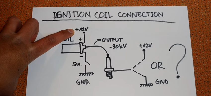
In summary, It is not difficult to wire an ignition system/diagram. First, connect the positive terminal of the ignition coil to a 12V battery and the negative terminal (of the ignition coil) to the switching unit and then to the ground. Next, connect the output section of the ignition coil to the spark plug. Finally, link the body of the spark plug to the +12 volts (for a -30kW spark plug), and then to the ground.
How to Wire a Conventional Ignition System
There are different types of ignition systems in various automobiles. Nonetheless, they all adhere to the conventional principles that describe their components and functioning mechanisms.
Step 1: Assemble the Components of the Ignition System
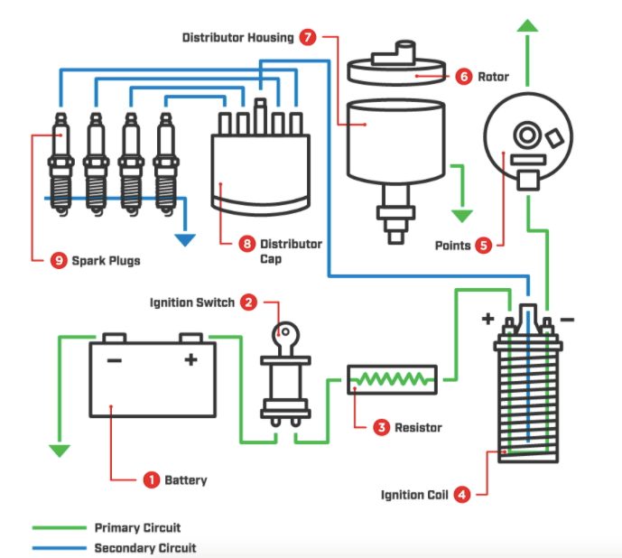
A conventional ignition system consists of the following components;
- Battery (mostly 12 volts battery)
- Ignition switch
- Resistor
- Ignition coil
- Points
- Rotor
- Distributor housing
- Distributor Cap
- Spark plugs
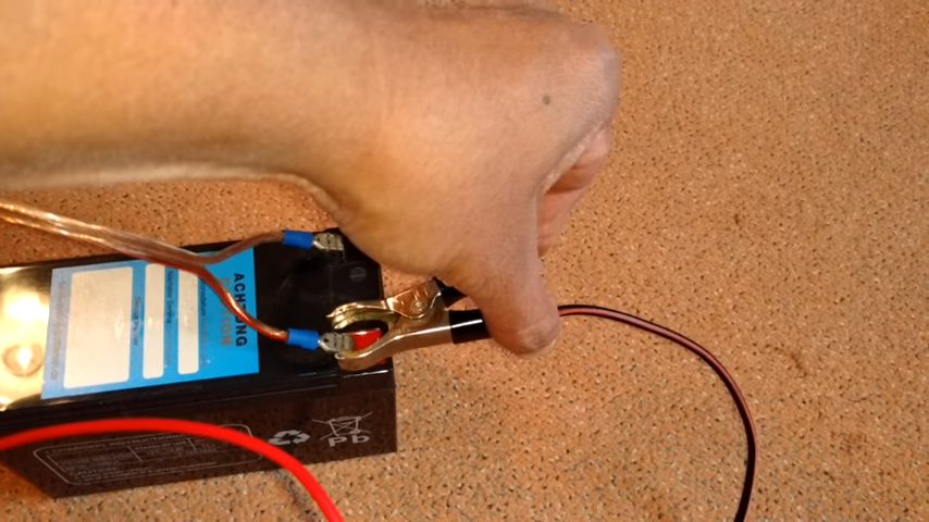
Step 2: Connect the Ignition System to a Battery
To connect the battery (12 volts) to the ignition system, link the positive terminal of the battery to the positive end of the ignition coil.
After you have done that, go ahead and connect the negative terminal of the ignition coil to the switching unit and then to the ground.
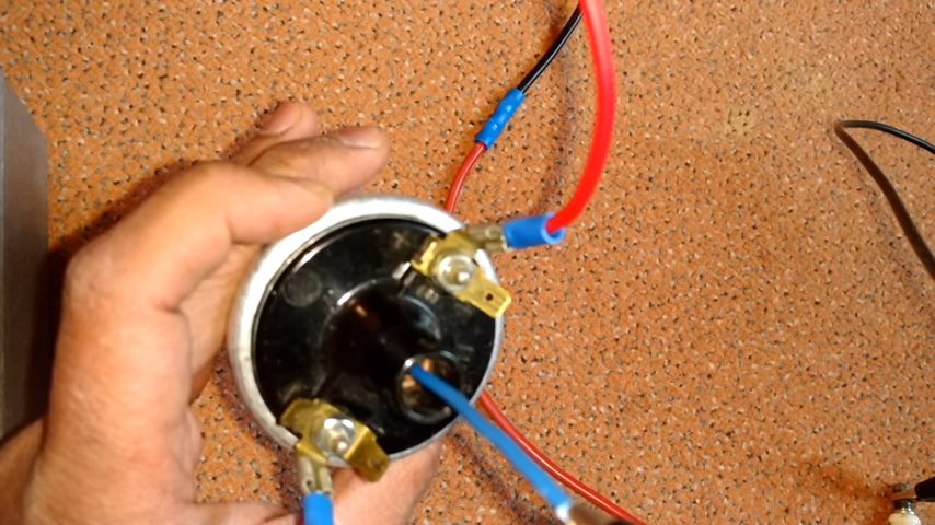
Step 3: Connect the Ignition Coil to the Spark Plug
Next, connect the output section of your ignition coil to the sparking plug.
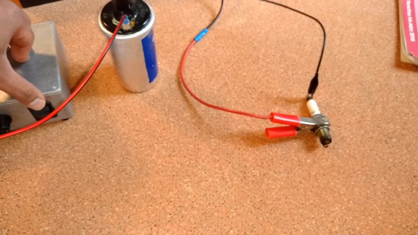
Step 4: Attach the Spark Plug to the Positive Terminal of the 12-volts Battery or Ground
And then complete the wiring by attaching the body of the spark plug to the positive terminal of the 12 volts battery (for a 30kW sparking plug). You may also connect the body of your spark plug to the ground and not to the positive terminal of the 12 volts battery.
It is important to note that if the output of your ignition coil is -30kW, then you can safely connect it to the +12 volts instead of grounding it. That will allow the ignition system to use every bit of the voltage on the spark plug.
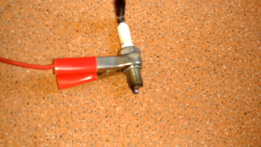
Step 5: Turn on the Igniter
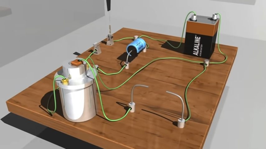
Simply flip the igniter button to supply power to the circuit. Whether you connected the spark plug to the ground or the positive terminal of the battery, the system will work and you will not see any difference. The spark will ignite as demonstrated below:
Additionally, you can check the polarity of your spark plug output to verify if it is positive or negative using a diode rated at 20kV – or any other ideal rating.
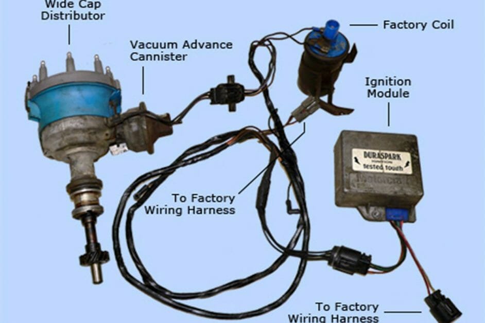
Electronic Ignition System
The wiring of an electronic ignition system is similar to that of the conventional system. The difference is in the components of the systems, and it is slight.
The electronic ignition systems have reduced emissions, higher mileage, and greater reliability. They have their breaker points replaced with a pickup coil (sensor), and an electronic ignition control module.
The entire circuit of the electronic ignition system resembles the conventional one. The armature revolves past the sensor to turn the primary current on and off. The armature creates a voltage that signals the module to turn on and off. When the coil has collapsed, the module timing will turn on the current to repeat the cycle.
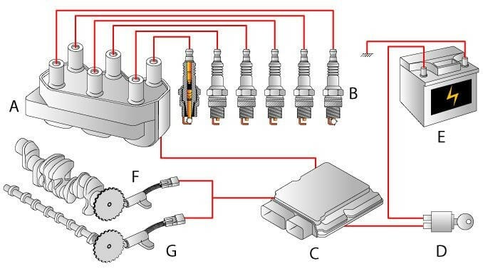
Distributor-less Ignition System
This is the newest type of ignition system and it is different from both the conventional and electronic ignition systems. The coils sit right on top of the spark plugs, and there are no spark wires. It is an electronic system.
A distributor-less ignition system has the ignition module and the engine computer, which controls the spark plug timing. They may have either one coil per cylinder or for each pair of cylinders.
The advantages of a distributor-less ignition system are as follows:
- There are no timing adjustments
- The rotor and the distributor cap are not available
- There are no moving parts to wear out through friction – the system is electronic
- There is no moisture accumulation – no distributors
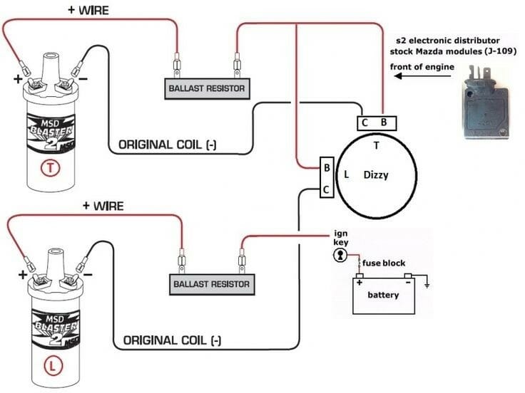
Types of Ignitions and Their Wiring Diagrams
Conventional Breaker-points Ignition Systems
Electronic Ignition Systems
Distributor-less Ignition Systems
Coil-on-plug Ignition Systems
How Does the Ignition Coil Work?
We will now learn how an ignition works in the ignition system of automobiles. The primary goal of the ignition coil is to generate sufficient voltage required to create a spark. The spark then flare-ups the fuel. The ignition coils use the relationship between electricity and magnetism to produce very high voltages.
The electrical current flows through a conductor such as a coil and creates magnetic flux (or magnetic field) around it (the coil). The magnetic flux stores charge which can be converted back to electricity. The magnetic field increases progressively as the current flows rapidly through the coil until it reaches a stable state. When the current supply is cut off (switched off), the magnetic fields collapse into the wire. (1)
The 12 volts battery powers up the primary coil on the spark plug, and then the primary coil induces a voltage on the secondary coil (still on the spark plug). The induced voltage is not enough to create a spark. So, when the switch is turned on, a change in the magnetic field occurs. The voltage spike on the secondary coil becomes greater since it has more turns of the coil. That is the voltage spike that will create thousands of volts which will in turn cause the spark plug to fire and ignite the fuel.
The purpose of the capacitor in the circuit is to absorb some of the excess voltage and prevent damages the voltage spike might cause. The voltage spike can spread in the ignition unit (if not absorbed) and burn the ECU. The ECU is one of the major components of the ignition system. (2)
Take a look at some of our related articles below.
- How to test ignition coil with multimeter
- How to test spark plug wires without multimeter
- How to connect ground wires together
References
(1) magnetic flux – http://hyperphysics.phy-astr.gsu.edu/hbase/magnetic/
fluxmg.html
(2) burn – https://www.urmc.rochester.edu/encyclopedia/content.aspx?ContentTypeID=90&ContentID=P09575
Video Reference