14 min read
How to Wire Multiple GFCI Outlets on One Circuit (4 Phases)

You can wire multiple GFCI (Ground Fault Circuit Interrupter) outlets by daisy-chaining them.
Key Takeaways: Wire the first GFCI outlet like a regular one. Connect the black (hot) wire from the next outlet to the brass terminal on the LINE row, the white (neutral) wire to the silver terminal on the LINE row, and the bare/green (ground) wire to the ground terminal.
Then, connect the LINE wires of each GFCI outlet to the LOAD row on each subsequent one. Connect its hot and neutral wires to the corresponding terminals on the LOAD row. Combine all ground wires using a wire connector and connect them to the single ground terminal on each GFCI outlet.
For the final GFCI outlet, connect the power supply wires to the LINE row terminals and the ground wire to the ground terminal.
So you have to connect each set of five wires to five terminals at each GFCI location, except for the first one on the circuit, which will have 3 wires to connect only to the line row plus the ground terminal.
If it seems confusing, I’ve separated the whole procedure into 3 wiring phases and also mentioned what to do before and after them, so read further before you start wiring.
GFCI Outlets
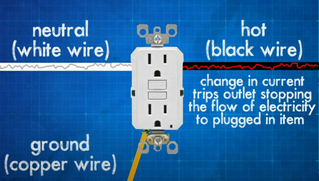
GFCI outlets provide additional protection compared to regular power outlets.
They protect against electrical shock if a faulty appliance is plugged in by sensing minor current fluctuations and shutting off the power in a fraction of a second (~1/40) [Black & Decker, 2008].
For instance, a GFCI outlet can protect a person from getting electrocuted by detecting the current interruption when a hairdryer drops into water and instantly cuts the power. It can detect a current surge or imbalance quicker than a circuit breaker. This safety aspect makes GFCI outlets ideal for kitchens, bathrooms, garages, and outdoor areas, generally, any moist or wet area.
However, I recommend using GFCI outlets throughout your home, or at least in the most hazardous areas. They are worth using, although larger and costlier than regular outlets.
Why Wire Multiple GFCIs on the Same Circuit?
Can you use more than one GFCI in the same set of connected outlets with GFCI protection?
You can wire multiple GFCI outlets on the same circuit, but consider the implications.
The wiring procedure will be the same as when wiring a regular outlet to a GFCI one.
However, wiring multiple GFCI outlets on the same circuit is usually unnecessary because one GFCI outlet should be sufficient to protect it entirely. They work more effectively when wired to protect a single location due to their high sensitivity.
Single-location GFCI outlets also avoid ‘phantom tripping’, which happens when power is shut off because of a tiny (but normal) fluctuation in current. [Black & Decker, 2008] Wiring multiple GFCIs on the same circuit will increase the chances of tripping. But don’t automatically assume the source of the problem is one of the GFCI outlets, as it might be a connected appliance [Family Handyman, 2017].
Wiring GFCI Outlets
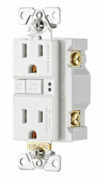
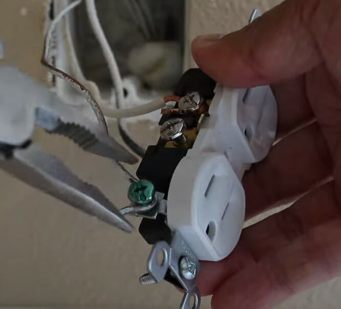
GFCI outlets follow the same wiring scheme as regular ones, but you will see two terminals marked ‘hot’ or ‘black’ and two marked ‘neutral’ or ‘white’, each marked as LINE and LOAD, and a common ground terminal.
Terminals
Normally, you will see bronze screws on the live terminals, silver ones on the neutral terminals, and a green screw on the ground terminals.
Wires
There are three types of wires:
- The black or red wires are for the live or hot connections. They either power the main GFCI outlet, come from the adjacent GFCI outlet, or bring electrical current into the load line.
- The white or gray wires are for the neutral connections. They provide a path for the current to return.
- The ground wires used for the connection are green, green with yellow stripes, or bare copper. They protect against ground faults caused by short circuits.
Each of the three types of wires must be connected to the right terminal – the hot ones to the bronze terminals, the neutral ones to the silver terminals, and the ground wire to the common ground terminal.
This wiring scheme is according to the US wiring system for domestic AC. The colors and terminals, including the outlet’s design, may differ if you live elsewhere.
Wiring Multiple GFCI Outlets
We will wire the GFCI outlets in three phases, plus a pre-wiring and post-wiring phase:
- Pre-Wiring – The things to do before you start wiring.
- First GFCI Outlet – One GFCI outlet will connect to only one other GFCI outlet.
- Intermediate GFCI Outlets – One or more GFCI outlets will connect to other GFCI outlets on both sides.
- Last GFCI Outlet – One GFCI outlet will connect directly to the main power source and the first additional outlets.
- Post-Wiring – The testing phase.
You can wire either 1 or 3 first or last. It doesn’t matter, but we will stick to the above order to show how to wire multiple GFCI outlets together to connect the power source at the end.
Phase 1: Initial Steps (Pre-Wiring)
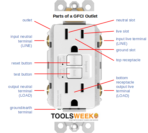
Firstly, ensure you can identify the LINE and LOAD rows for the hot/live and neutral terminals on the GFCI outlets.
For personal safety, you must turn the power off to the circuit before starting.
Switch off the circuit breaker for the circuit you will be working on. Use a tester to ensure no current is flowing.
Wear gloves while working with live electricity.
Phase 2: Wiring the First GFCI Outlet
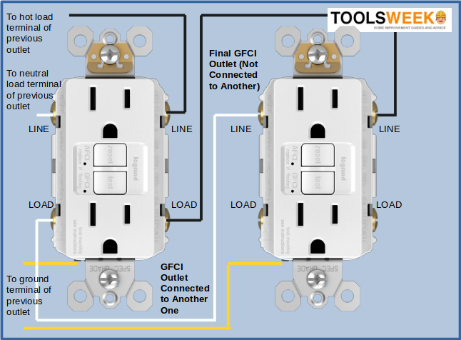
Follow the wiring diagram below to connect the first GFCI outlet to a second one.
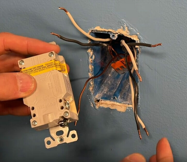
Our first outlet is the “final GFCI outlet” shown here on the right, which is neither connected by a further outlet (as an additional load) nor a power source (directly). It only takes two wires from the load terminal of the next outlet (on the left) and connects them to its line terminals, plus the ground connection.
Before installing the first GFCI outlet, ensure the box is the right size and set firmly inside the wall. The wires should extend at least 4-6 inches from the box. Strip their ends about half an inch.
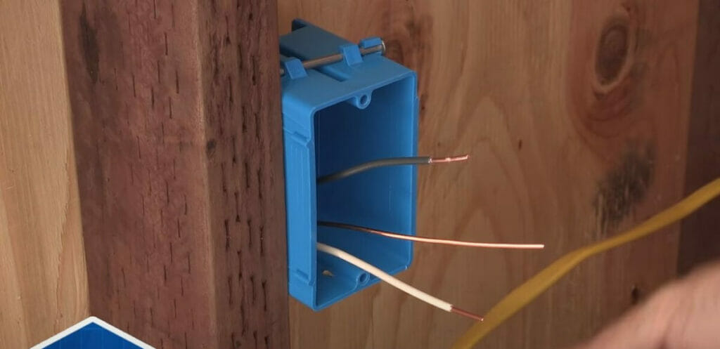
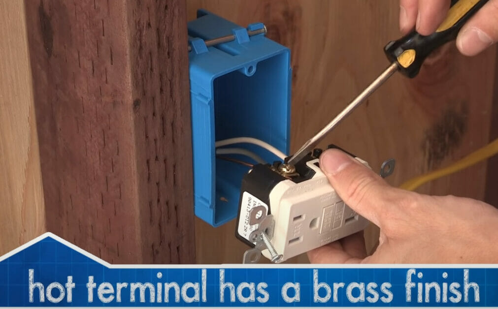
Attach the wires to the GFCI’s terminals (or connectors) as follows:
- Connect the black wire to the brass screw on the terminal marked ‘Hot’ or ‘Black’.
- Connect the white wire to the silver screw on the terminal marked ‘Neutral’ or ‘White’.
- Connect the ground wire to the green screw on the terminal marked ‘GRD’ or ‘Ground’.
The hot and neutral wires (black and white) must connect to the LINE row, not the LOAD row.
Use nose pliers if you need to wrap a wire around its terminal. If the ground wire is bare copper, ensure it doesn’t touch other terminals.
These wires you connected (hot and neutral ones) will go to the LOAD terminals of the next outlet.

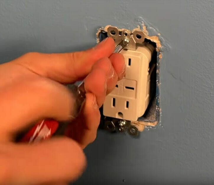
After wiring the GFCI outlet, attach it to the box and cover plate and ensure all the screws are tight.
Phase 3: Wiring Additional GFCI Outlets
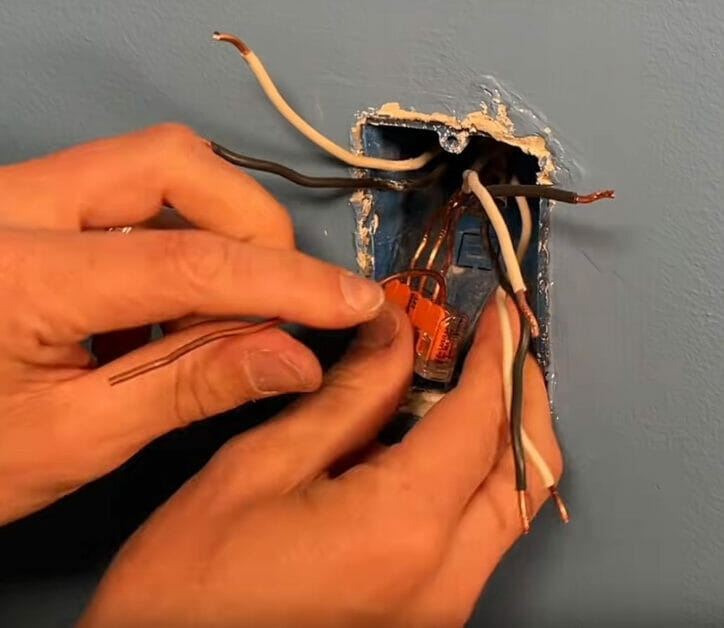
When wiring multiple GFCI outlets together, we use all five terminals on them as follows (see the diagram below):
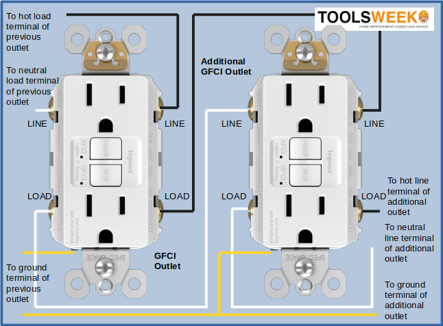
Connect multiple GFCI outlets together in a parallel arrangement, whereby the LOAD terminals of the additional outlets are connected to the LINE terminals of the preceding one. All black wires are connected to hot (aka live) terminals, all white wires to neutral terminals, and all green or bare wires to the ground terminals.
So, one pair of wires (hot and neutral) will connect to the LINE terminals, while the other pair will connect to the LOAD terminals. The illustration above shows the last GFCI outlet connected to the last one, which connects to the power supply.
If you cannot see the load terminals, they might be covered by a yellow sticker if the GFCI outlet is new. As for the ground wires, they will be pigtailed together and connected to the single green/ground terminal.
Repeat this pattern for all additional outlets before reaching the last one on the circuit.
You can also apply the same method of combining wires when connecting another GFCI outlet, i.e., black with black, white with white, and ground with ground.

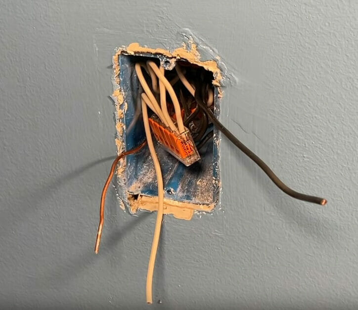
Tuck the interconnected wires inside the box.
Phase 4: Wiring the Last GFCI Outlet
The procedure is the same for wiring the last GFCI outlet as in the previous phase, except that:
The line terminals of the main source GFCI outlet are connected to the main electricity supply.
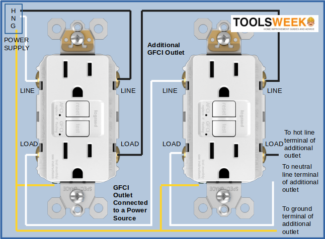
As shown in the wiring diagram above, connect the power source wires to the LINE terminals on either side – the black wire to the hot/live terminal and the white wire to the neutral one when connecting the last outlet:
- Connect the black (hot/live) wire to the brass terminal marked ‘Hot’ or ‘Black’ on the LOAD row and the one from the power cable to the LINE row.
- Connect the white (neutral) wire to the silver terminal marked ‘Neutral’ or ‘White’ on the LOAD row and the one from the power cable to the LINE row.
Now, you might ask what to do with the remaining bare copper or ground wires, as there’s only a single terminal marked ‘GRD’ or ‘Ground’. Use wire connectors to connect all the ground wires together and connect them to the ground terminal, as you did before in Phase 2.
Phase 5: Testing (Post-Wiring)
When all the GFCI outlets are wired, inserted, and attached, and the cover plates are on, they’re ready to use.
You can now give power to them by switching the breaker on again. However, multiple GFCI outlets wired together will require testing for power, frequent tripping, and identifying the source of problems.
Each GFCI outlet has two buttons, ‘Reset’ and ‘Test’. You can press these to reset and test the outlet, respectively. You can also use an instrument to test a GFCI, such as a GFCI outlet tester, a voltage or current tester, and a multimeter. Besides testing for power, you might also have to deal with a problem, such as frequent tripping and testing multiple locations if other outlets are connected to the same GFCI.
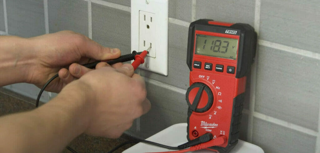
As with a regular voltage tester, you can use a multimeter to test the voltage or current levels. However, a multimeter will give you an exact reading, making it more informative.
Set the multimeter to an appropriate range for what you want to measure. For example, ensure the selected range covers up to 120 volts to measure AC voltage.
Be careful when using a multimeter: Don’t touch the metal prongs while testing.
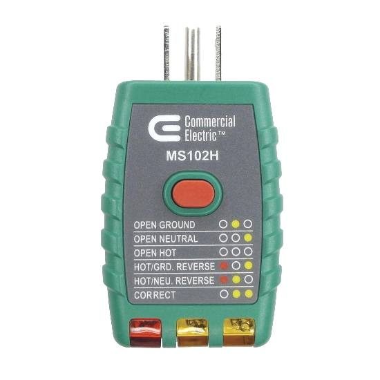
You can also use an instrument called a GFCI outlet tester or GFCI receptacle tester for a more thorough diagnosis if necessary.
It’s a simple electrical device with LED light indicators. Advanced models might also have a display. A GFCI tester can check whether an outlet has been wired correctly. It is useful because it identifies common wiring problems, including open hot, neutral, or ground, reverse polarity, and reversed hot or ground.
To use a GFCI tester, plug it into the outlet and note the indicator lights. It should have a guide (like the one below) to show what different combinations of lights indicate.
References
Books:
- Black & Decker. The Complete Guide to Wiring: Upgrade Your Main Service Panel – Discover the Latest Wiring Products – Complies with 2008 NEC. Black & Decker Complete Guide. Editors of Creative Publishing International. Cool Springs Press. 2008
- Family Handyman (Editors). Volume 1 of Family Handyman DIY Basics. Simon and Schuster, 2017
Website Resources:
- Home Depot. GFCI tester. https://www.homedepot.com/p/Commercial-Electric-Outlet-Tester-with-GFCI-OTG-102R/206029151
Video References:
AMRE Supply

Everyday Home Repairs
MrFixItDIY
TheRenderQ