16 min read
How to Wire an Outlet from Another Outlet (2 Methods & Steps)

Wiring an additional outlet from an existing one may be a convenient option, but how is the wiring done?
If you’re comfortable wiring single outlets, you can extend the circuit to add another one. As long as it’s a shared circuit and the wire and circuit breaker’s ampacity support it, you can easily connect them.
I will show you five scenarios and the wiring procedure in detail for two: wiring an additional regular outlet to an existing one and a GFCI outlet.
Requirements and Precautions
Requirements
You will need the following equipment and tools:
- Equipment: an extra outlet and box, a cable long enough to stretch from the main outlet to the second outlet (see under ‘cabling’ below), two small pieces of black and white wire, one wire cap, and two wire connectors
- Tools: screwdriver, nose pliers, non-contact tester, tape measure, wire stripper, wire staples
Precautions
Turn the power off at the panel (by switching the circuit breaker off) before opening the main outlet and rewiring it.
Assumptions
This project assumes you have an existing wired outlet and want to connect another outlet to it.
Considerations
Note that you can only extend a circuit by attaching an extra outlet if it’s a shared circuit. If it’s a dedicated circuit, you should NOT attach another outlet to it.
Also, before you start connecting the second outlet, have you considered the power limitations of the circuit?
Can the circuit handle the extra load? The answer depends on what you will plug into both outlets. The total current draw should not exceed the circuit’s ampacity. The relationship between the wattage (power) and amperage (current) is amps = watts / 120 (for a 120V system).
For example, if it’s a 15-amp circuit, the maximum current should not exceed 10-12 amps (or 80% of 15 amps).
Positioning
As for positioning, if the secondary outlet is horizontally displaced, it should normally be at the same height as the primary one to look nice. If it’s vertically displaced, ensure they are aligned vertically.
Cabling
If the outlets are on a 15-amp circuit, use a 14/2 cable with a ground wire, and if it’s a 20-amp circuit, use a 12/2 cable with a ground.
Wiring an Outlet from Another Outlet
I will show you two ways to wire an outlet from another outlet:
- Adding an extra regular outlet, i.e., a regular outlet connected with another regular outlet.
- We are adding a regular outlet to a GFCI one.
I’ve also given recommendations for three other scenarios – when you want to add another outlet nearby when adding an outlet back-to-back, and when adding one outdoors.
Method 1: Adding an Extra Regular Outlet
This method is for adding another regular outlet to an existing one.
Step 1: Extend a Cable between the Two Outlets
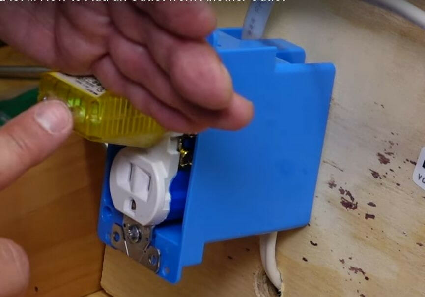
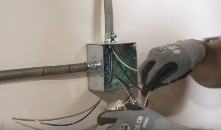
For a demonstration using open wiring, the extra regular outlet is connected to the first outlet by an additional cable running from one to the other, as shown below.
You may need wire staples to fix the cable, especially if it’s exposed. The run will be as long as it needs to be within the wall to connect the two. The cable which the man is holding is the power supply cable (with the power off).

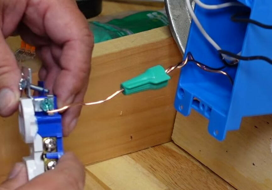
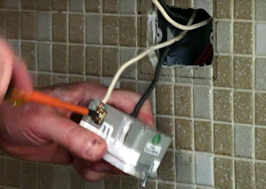
Step 2: Combine and Connect the Ground Wires
Combine the two ground wires using a wire cap or connector.
Curl the end of the ground wire sticking out, using nose pliers, to form a hook and connect it to the green screw of the outlet’s ground terminal.
Step 3: Combine and Connect the Hot Wires
Combine the two hot wires using a wire connector, as shown. Extend a small third piece of black wire from the connector to the outlet’s brass terminal.
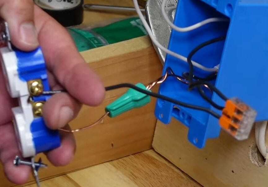
Note that a shunt connects two terminals on each side. Although you could connect both wires directly to the outlet (one on each brass terminal), using a connector instead is recommended to prevent overheating.
Step 4: Combine and Connect the Neutral Wires
Do the same as you did for the hot wires to the neutral ones, i.e., combine and connect the two neutral wires to the outlet’s silver terminal using a small third piece of white wire.
Ensure all the connections are tight.
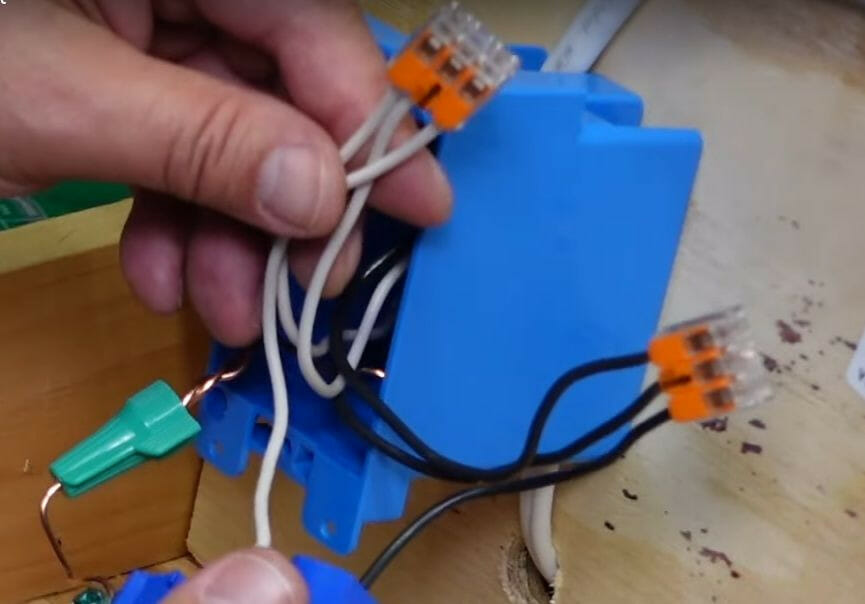
Step 5: Attach the Main Outlet
The main outlet is now wired, so tuck all the wires inside the box and attach the outlet to the box.
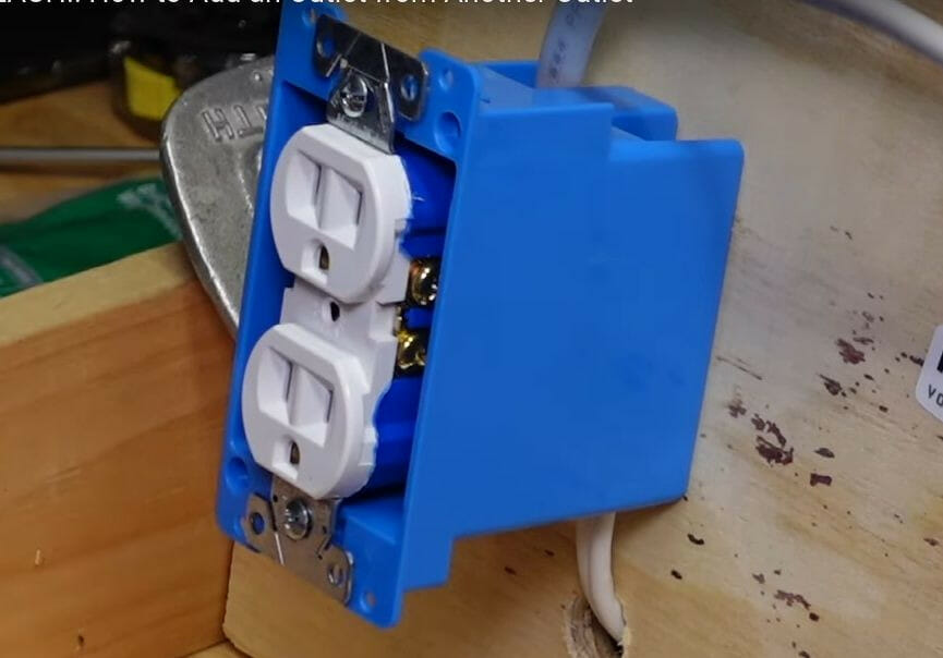
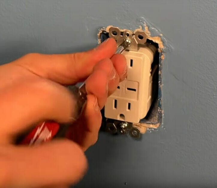
Step 6: Connect and Attach the Second Outlet
Connect and attach the second outlet likewise but directly to the outlet’s terminals.
You don’t need to use wire caps or connectors because there’s only one cable with three wires, all of which will connect directly. Connect the black wire to the brass terminal, the white one to the silver terminal, and the bare one to the ground terminal.
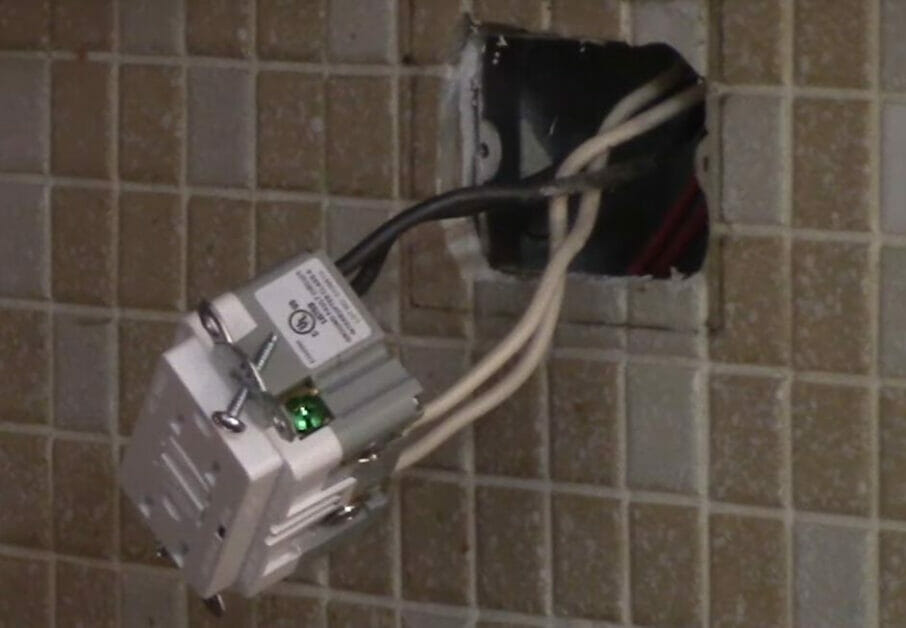
Step 7: Turn the Power On
Both outlets are now wired and connected to their respective boxes.
So, you are now ready to turn the power on.
Step 7: Test the Outlets
It’s a good idea to test both outlets before using them.
The light tester shown below lights up in green when there is power, so the first outlet is fine. The same was true for the second outlet, so both are ready to use.
Method 2: Adding a Regular Outlet to a GFCI One
A GFCI outlet is specially designed to connect it to another outlet so that it can provide the connected (regular) outlet the same kind of protection.
A regular outlet is commonly attached to a GFCI outlet in kitchens, bathrooms, garages, and outdoor sites. As an example, here’s a pair of connected outlets above a kitchen counter:
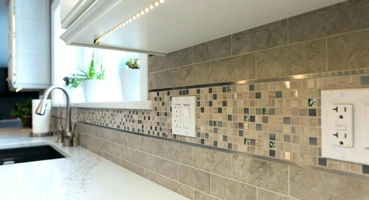
The main outlet is the GFCI one on the right, and the secondary one on the left.
The wiring is similar to how regular outlets are connected, except that the GFCI outlet has separate terminals for the extra load. The two outlets are connected internally, as shown in the diagram below.
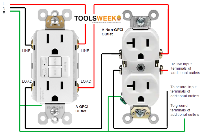
The power supply wires connect to the line terminals, and the cable from the second outlet is connected to the GFCI outlet’s load terminals. I’ll show you how it’s done step-by-step below.
Before that, note and observe the following:
- The power to the circuit you will work on must be switched off at the main panel.
- As in Method 1, open the existing GFCI outlet and extend a cable from its box to the location of the other box and set the second box in place.
- Identify the line and load terminals on the GFCI outlet. The original power supply cable’s wires should be connected to the line terminals if it was already connected.
Follow these steps when you are ready to rewire the GFCI and second outlets:
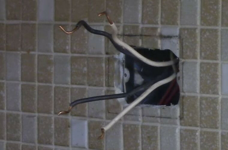
Step 1: Strip the Ends of the Second Cable
Strip the ends of the second cable about 4-6 inches out from the box. Here, the first GFCI outlet was completely removed, although it’s not necessary to do that, as you might forget which cable is which.
Step 2: Connect the Line Wires
In this step, you will wire the GFCI outlet.
Connect the power supply (LINE) cable wires to the LINE row. See the wiring diagram I gave earlier. Attach the LINE wires to the GFCI’s terminals (or connectors) as follows:
- Connect the black wire to the brass screw on the LINE terminal marked ‘Hot’ or ‘Black.’
- Connect the white wire to the silver screw on the LINE terminal marked ‘Neutral’ or ‘White.’
The power supply wires (black and white) must be connected to the LINE row, not to the LOAD row. If you didn’t completely remove an existing GFCI outlet, the line wires will already be connected, and if the GFCI terminal is new, the load terminals will probably be covered by tape.
When wrapping a wire around its terminal, use nose pliers to form a hook. If the ground wire is bare copper, ensure it doesn’t touch any other terminals.
Step 3: Connect the Load Wires
The wires in the new cable you extended from the GFCI outlet to the secondary outlet will connect to the LOAD terminals.
- Connect the black wire to the brass screw on the LOAD terminal marked ‘Hot’ or ‘Black.’
- Connect the white wire to the silver screw on the LOAD terminal marked ‘Neutral’ or ‘White.’
This is how it should look on the side of the main GFCI outlet:
Step 4: Connect the Ground Wires
The remaining wires are the two bare copper or ground wires.
Use wire connectors (or wire caps) to combine them and then connect them to the single ground terminal marked ‘GRD’ or ‘Ground,’ which usually has a green screw. Do the same as in Step 2 of Method 1.
Ensure all the terminals of the GFCI outlet are tight before attaching it.
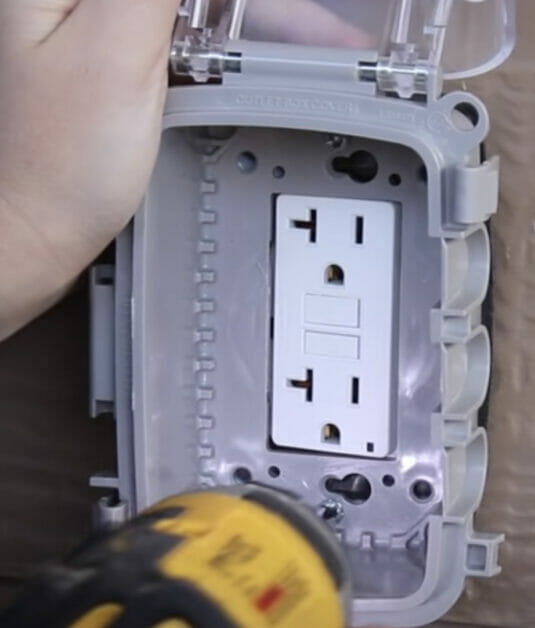
Step 5: Attach the GFCI Outlet
The GFCI outlet is now wired, so attach it to the box and cover plate.
Step 6: Wire the Secondary Outlet
The secondary outlet will be a regular one, with only one cable.
The cable carries power from the GFCI outlet to the secondary outlet. A single cable and no load terminals to worry about, make it easier to wire. Wire the secondary outlet as follows:
- Connect the black wire to the brass screw on the terminal marked ‘Hot’ or ‘Black.’
- Connect the white wire to the silver screw on the terminal marked ‘Neutral’ or ‘White.’
- Connect the bare wire to the green screw on the terminal marked ‘GRD’ or ‘Ground.’
Step 7: Attach the Secondary Outlet
Attach the secondary outlet to its box after it is wired.
Step 8: Power the Outlets
Once both connected outlets are wired, you can safely power the circuit back on.
Step 9: Test the Outlets
As in Method 1, I recommend testing both outlets before using them. Follow the same procedure as given in Step 7 for Method 1.
You should also retest the GFCI outlet’s tripping capability by plugging in a load and pressing the TEST button. The power to the load should be cut immediately. If so, the GFCI outlet is doing its job properly. You can do the same to the other outlet because connecting it to the GFCI one was to give it the same protection.
After testing both connected outlets, press the RESET button on the GFCI one to resume normal operation.
Recommendations
Adding an Outlet Nearby
When adding an outlet nearby (with external wiring), the wiring procedure will be the same as explained in detail in the first two methods above.
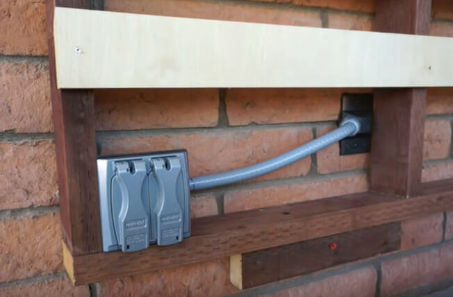
So, I’ll show you how to set the second outlet in place using a conduit instead of wiring. Here are my recommendations:
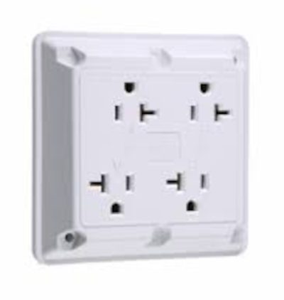
- If the second outlet is very close, consider a larger box and outlet with multiple receptacles instead.
- Use conduit for exposed wiring, even if it’s a short run.
Adding an Outlet Back-to-Back
Adding a second outlet back-to-back with the primary one should be easier as it will require less wiring.
The wiring procedure will be the same as explained in detail in the first two methods above. So, I’ll focus on showing how to set the second outlet in place instead. Here are my recommendations:
- Carefully mark the spot for the secondary outlet so the hole will be exactly where you want it. Take all necessary measurements. Use a stud finder if necessary to ensure you drill away from a stud.
- Drill a hole from the existing outlet to the other side (not the other way around). Drill at a slightly downward angle.
- Use an LB fitting to ensure a watertight transition (see below).

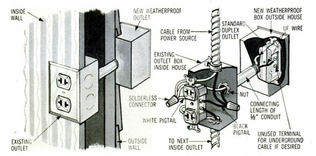
Adding an Outlet Outdoors
When installing the additional connected outlet outdoors, I recommend you use a weatherproof cover. Also, keep the cable covered inside a conduit (see Method 3).
There may be situations when you need to use two or more of the above.
For example, if you’re wiring to an outlet on the other side of an external wall, and it’s not exactly right behind, you will need a watertight seal, conduit, and a weatherproof cover, as in the example below.
References
20-amp Quad-receptacle. https://www.legrand.us/wiring-devices/outlets-and-receptacles/commercial-receptacles/specification-grade-quad-white/p/420w
ArchAngel Electric. https://archangelelectricinc.com/services/
LB Fitting. https://kent.ca/1-2-cast-aluminum-gray-type-lb-conduit-body-1013622
Popular Science. Vol. 171, No. 1. Published by Bonnier Corporation. https://www.legrand.us/wiring-devices/outlets-and-receptacles/commercial-receptacles/specification-grade-quad-white/p/420w
Video References
April Wilkerson
Crafted Workshop
Everyday Home Repairs
FIX IT Home Improvement Channel
Granworks Workshop
HandyDadTV