9 min read
How to Wire a GFCI Outlet (6 Steps and Multi Guide)
Wiring a GFCI outlet is not difficult, but the extra terminals can be confusing.
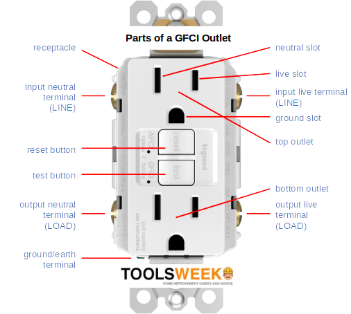
GFCI outlets follow the same wiring scheme as regular ones, but you will see two terminals marked ‘hot’ or ‘black’ and two marked ‘neutral’ or ‘white,’ each marked as LINE and LOAD. Additionally, you will see a ground terminal. So, how do you connect three wires to five terminals?
Quick Summary: A GFCI outlet can be wired like a regular outlet. Connect the black (hot) wire to the bronze terminal on the line row, the white (neutral) wire to the silver terminal on the line row, and the bare/green (ground) wire to the ground terminal.
The load row is for optionally connecting the GFCI outlet to additional loads to provide them with the same protection for which it is designed. Connect the corresponding hot and neutral load wires to the right terminals on the load row. Then, combine all the ground wires using a wire connector and connect them to the single ground terminal.
So you don’t connect three wires to five terminals after all. You only connect them to three (two line terminals and the ground one). You only use the two extra load terminals for extra loads.
I’ll explain in detail below.
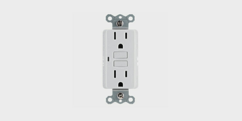
GFCI Outlets
A GFCI outlet is like an ordinary outlet but with extra protection against electric shock if you plug in a faulty appliance or device.
It senses minor fluctuations in current flow and shuts off automatically within a fraction of a second. This makes them ideal for kitchens, bathrooms, and outdoor areas.
Compared to regular outlets, GFCI ones are a bit larger and more expensive.
Wiring a GFCI Outlet
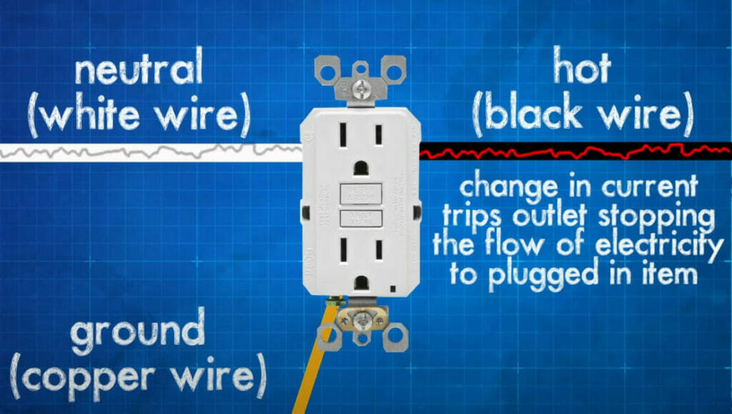
Normally, if it’s a standalone GFCI outlet, there are three wires to connect:
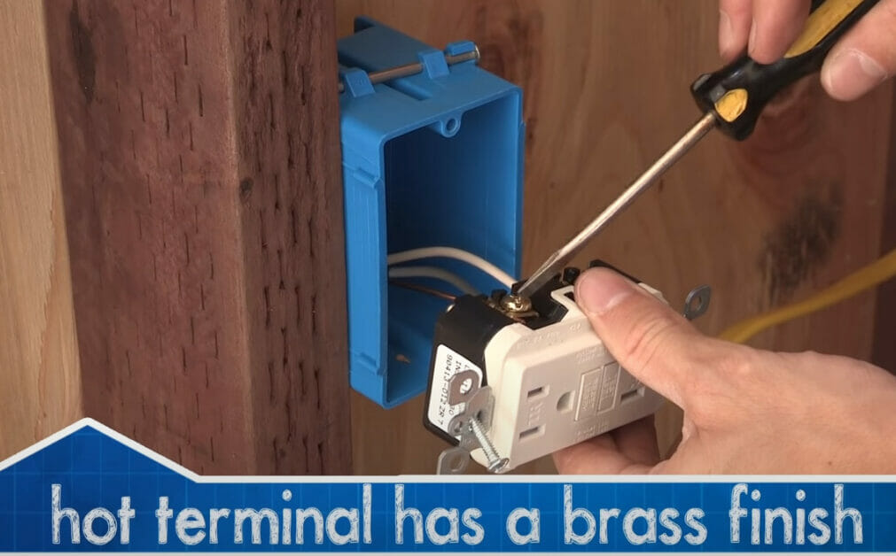
- A black wire, which is the hot wire that provides current to the attached load – It will connect to the GFCI outlet’s bronze terminal.
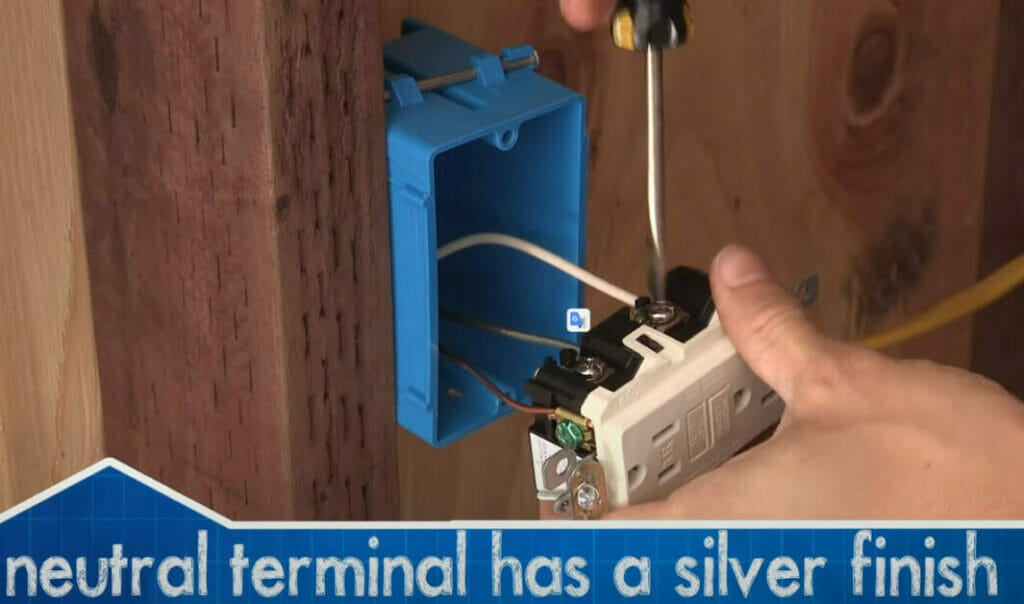
- A white wire, which is the neutral wire that provides a return path for the current – It will connect to the GFCI outlet’s silver terminal.
- A bare copper or green/yellow wire, which is the ground wire that provides an additional local grounding – It will connect to the GFCI outlet’s ground terminal.
GFCI outlets usually have screw terminals, but some might have wire connectors. Regardless, ensure you connect the right wire to the right terminal or connector.
The above wiring scheme is according to the US wiring system for domestic AC. The colors and terminals, including the outlet’s design, may differ if you live elsewhere.
Steps for Wiring a GFCI Outlet
Here are the steps for wiring a (standalone) GFCI outlet according to the above wiring scheme:
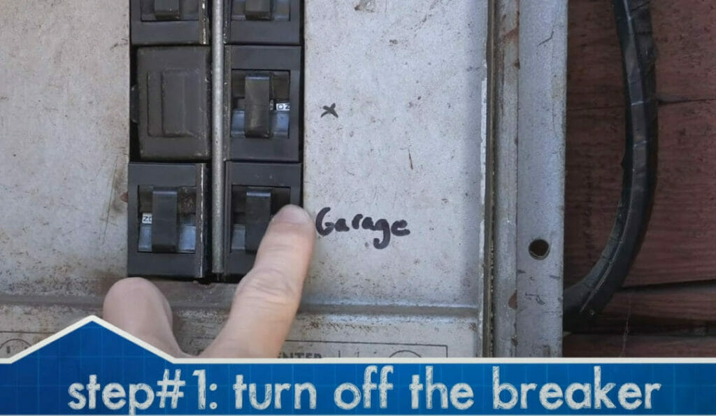
Step 1: Turn the Power Off
For personal safety, you must turn the power off to the circuit before starting.
Switch off the circuit breaker for the circuit you will be working on. Use a tester to ensure no current is flowing.
Step 2: Remove the Existing Outlet (if applicable)
This step only applies if you replace an existing outlet with a GFCI one; otherwise, skip it.
Remove the cover plate from the outlet by removing the screws on it. Then, gently pull it off and the outlet by holding its two opposite sides. Once out, disconnect the wires from the terminals at the back.

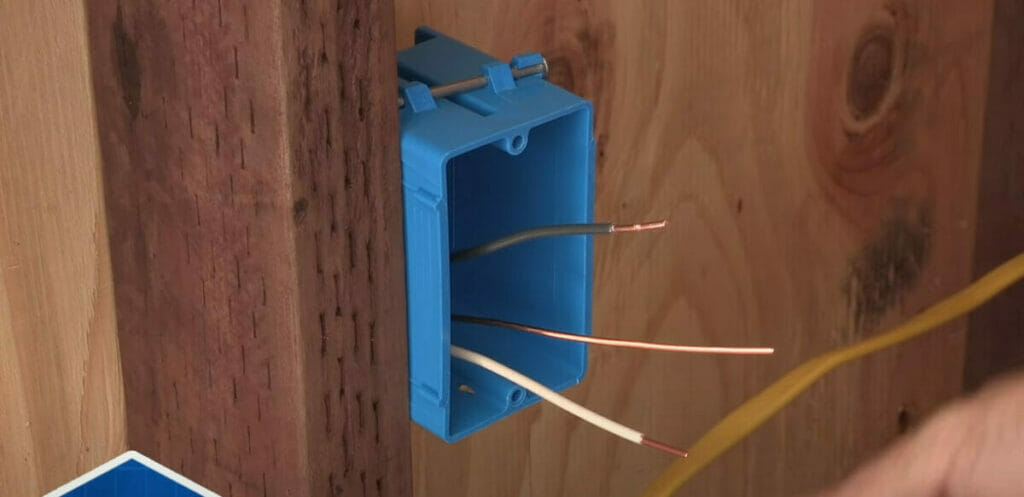
Step 3: Prepare the Box and Wire Ends
Before installing a GFCI outlet, ensure the box is the right size and set it firmly inside the wall.
The wires should extend at least 4-6 inches from the box. Strip their ends about half an inch.
Step 4: Attach the Wires
This is the main step where you will wire the GFCI outlet.
Attach the wires to the GFCI’s terminals (or connectors) as follows:
- Connect the black wire to the brass screw on the terminal marked ‘Hot’ or ‘Black.’
- Connect the white wire to the silver screw on the terminal marked ‘Neutral’ or ‘White.’
- Connect the ground wire to the green screw on the terminal marked ‘GRD’ or ‘Ground.’
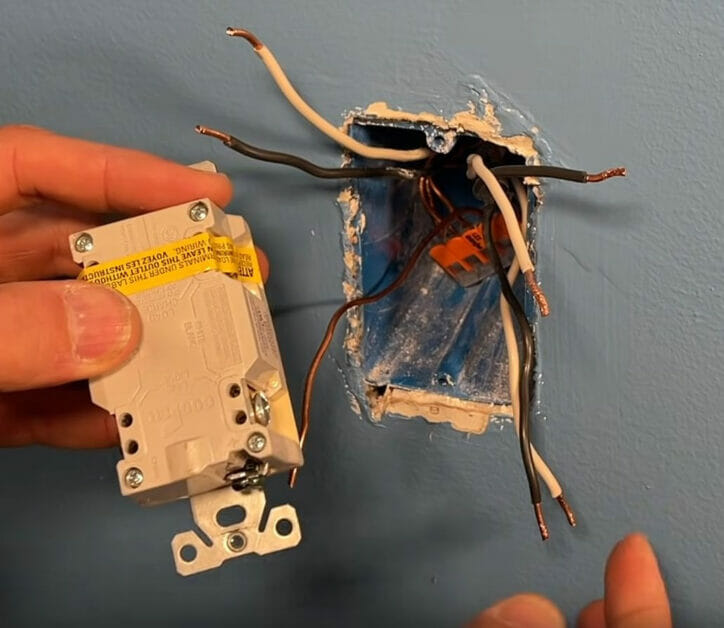
The power supply wires (black and white) must be connected to the LINE row, not to the LOAD row, which is for a different purpose (see below under ‘Connecting Multiple Outlets’). If the GFCI terminal is new, the load terminals will probably be covered by tape.
Use nose pliers if you need to wrap a wire around its terminal. If the ground wire is bare copper, ensure it doesn’t touch other terminals.
Step 5: Attach the GFCI Outlet
After wiring the GFCI outlet, attach it to the box along with the cover plate.
Ensure all the screws are tight.
Step 6: Power the Outlet On
When the GFCI outlet is wired, inserted, and attached, and the cover plate is on, it’s ready to use.
You can now give power to the outlet by switching the breaker on again.
Connecting Multiple Outlets
GFCI outlets can share their protection mechanism with other regular outlets.
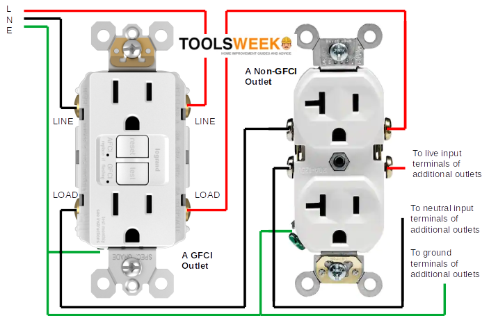
In a standalone GFCI outlet, you connect the hot and neutral wires to the LINE terminal. But when connecting multiple outlets (or loads), you will have additional sets of three wires to connect to the same outlet. That’s what the LOAD row was for. I’ll show you how to do it.
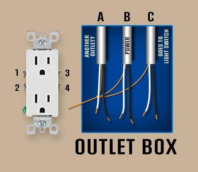
You will connect the wires from the power cable (marked B above) as before and accommodate the extra cables (marked A and C above) by treating them as loads under a parallel arrangement. You might see something like this:
Firstly, ensure you know the LINE and LOAD rows for the hot/live and neutral terminals. See the illustration below.
If connecting an additional outlet, connect the power cable wires to the LINE terminals on either side – the black wire to the hot/live terminal and the white wire to the neutral one.
Then, connect the hot and neutral wires from the other outlet’s line terminals (or another load, such as a light switch) to the GFCI outlet’s load terminals. So, to ensure you’ve done it properly:
- All black (hot/live) wires should only be connected to a brass terminal marked ‘Hot’ or ‘Black’, but the one from the power cable should be on the LINE row and the one from the loads to the LOAD row.
- All white (neutral) wires should only be connected to a silver terminal marked ‘Neutral’ or ‘White’, but the one from the power cable should be in the LINE row and the one from the loads to the LOAD row.
Now, you might ask what to do with the remaining bare copper or ground wires, as there’s only a single terminal marked ‘GRD’ or ‘Ground’. Use wire connectors to connect all the ground wires together and connect them to the ground terminal.
You can also apply the same method of combining wires if you are connecting multiple extra loads to the GFCI outlet.

The wiring of one additional outlet with a GFCI outlet will look as illustrated below.
References
GFCI outlet. https://www.walmart.com/ip/GE-15A-GFCI-Outlet-White-32073/52213771
Video References
CircuitBread
Everyday Home Repairs
MrFixItDIY
TheRenderQ