11 min read
How to Wire a Solid State Relay?
Do you need help wiring a solid-state relay? Below I’m going to teach you how I do it.
Using a solid-state relay for any operation gives you many options. These handy little devices can be used for electrical heaters, motor control, or small light fixtures. But wiring a solid-state relay can be daunting, especially if you aren’t experienced. That is why today, ill show you how to wire an SSR with a small light bulb and sensor.
In general, to wire a solid-state relay for an automatic light bulb:
- Understand the mechanism of the SSR.
- Connect phase supply to the SSR.
- Connect the bulb to the SSR.
- Grab the neutral wire and connect it to the bulb.
- Connect the SMPS and the sensor.
- Connect the sensor’s black wire to the terminal box.
- Connect the terminal box to the SSR.
- Connect the SMPS and SSR.
- Test the automatic bulb.
Continue reading below for an in-depth explanation.
9-Step Guide on How to Wire a Solid State Relay (SSR)
In this guide, I’ll explain how to wire an SSR to a light bulb and sensor. This article focuses on preparing an automatic light bulb that turns on and off upon object detection.
However, you can apply the same process to a temperature controller too. But I recommend starting with a simpler process, such as an automatic light bulb, before diving into the hard stuff.
Important: During this guide, I used blue, black, brown, and green wires for different connections. However, your home’s wiring color codes might vary according to the single or three-phase connection.
Remember, you always deal with hot, neutral, and ground wires, whatever the color code.
Things You’ll Need
- 3 – 32VDC solid state relay
- Suitable plug top
- Light bulb
- NPN sensor
- SMPS
- Small terminal box
- Few wires
- Flathead screwdriver
- Small wire stripper
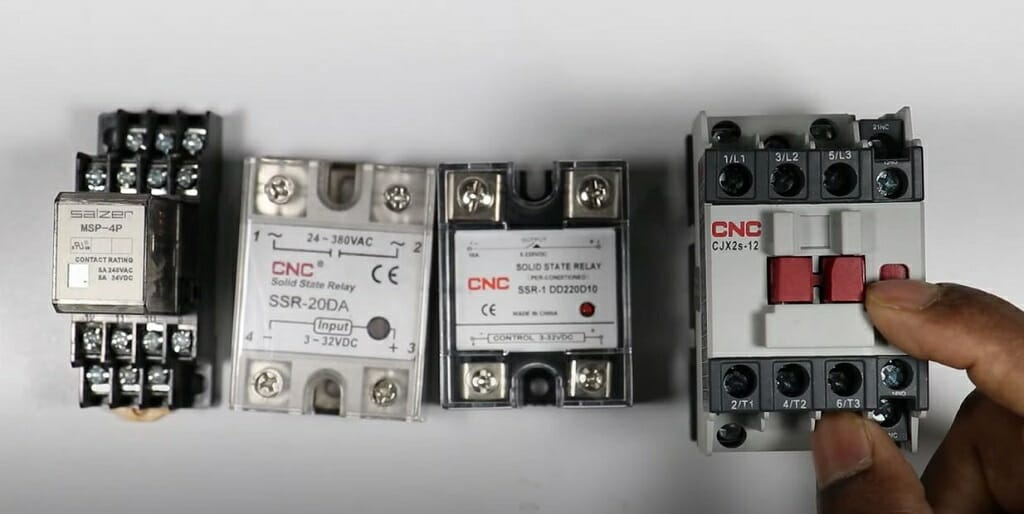
Step 1 – Understanding the Solid State Relay
Before getting started with the solid-state relay wiring, it is vital to understand the mechanism of the SSR. It will give a decent idea of what we are doing today.
In simple terms, SSR, aka Solid State Relay, is a switching device. These small devices can be used for many applications. But the basic concept of the device always remains the same. SSRs can turn on/off any circuit’s current, signal, or voltage. Hence, you can use these devices for applications such as temperature controls, motor control, lighting, etc.
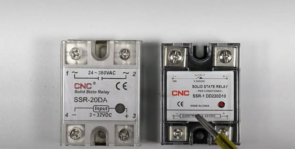
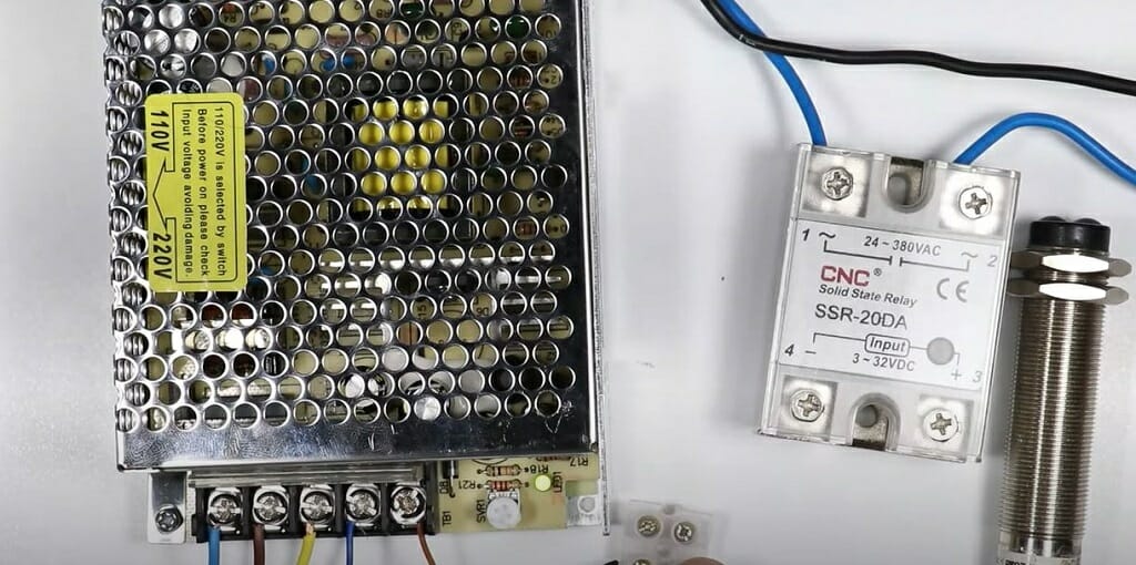
Mechanism of the SSR
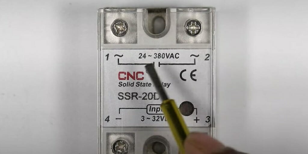
As you can see, SSR is a small device that has four different terminals. These terminals are labeled as 1, 2, 3, and 4. Terminals 1 and 2 are for the power supply. This means you can connect the input power to terminals 1 and 2. Terminals 3 and 4 are for the output connection.
I’m using a DC-to-AC solid-state relay for this process. Hence, DC power is provided to terminals 1 and 2. After that, terminals 3 and 4 provide the AC output, which connects to the light bulb and plug top.
Tip of the Day: Even though we use an AC to DC power supply, this type is not the only one. Depending on your requirement, you can use DC to AC, DC to DC, or AC to AC solid-state relay.
Step 2 – Connect the Phase Supply to the SSR
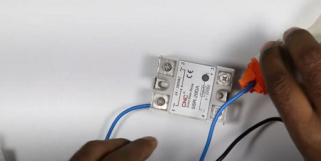
Now that you understand the SSR well, you can start the wiring process.
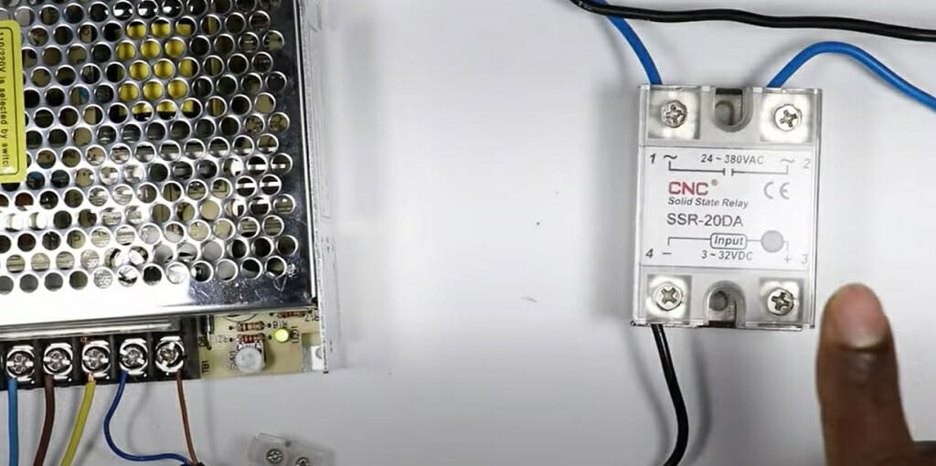
First, connect the plug top’s phase supply wire(blue) to terminal 1.
Step 3 – Connect the Bulb to the SSR
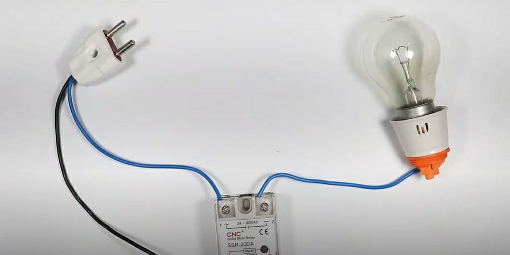
Then, connect terminal 2 to the light bulb using a blue wire (as shown in the image).
Step 4 – Complete the Neutral Connection
Next, connect the plug top’s neutral wire to the bulb’s neutral terminal.
These three steps complete the bulb and SSR connections. Now move on to step 5.
Step 5 – Connect SMPS and the Sensor
In this step. I’ll explain how to connect the SMPS and the NPN sensor. But before that, you need to understand these two devices.
What is SMPS?
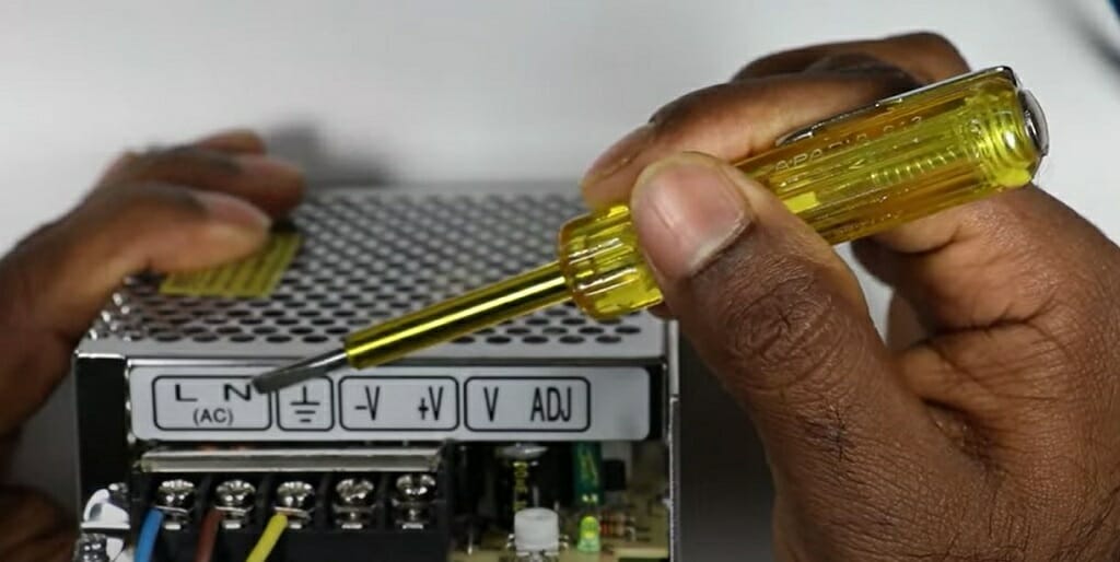
SMPS, aka Switched Mode Power Supply, is a small power supply device that can convert DC to AC or AC to DC power. I use an AC-to-DC SMPS device since the main power supply is AC. And sensor and the solid-state relay operate on DC power. This device is very similar to your computer’s power supply. It also converts the AC to DC power.
What Is an NPN Sensor?
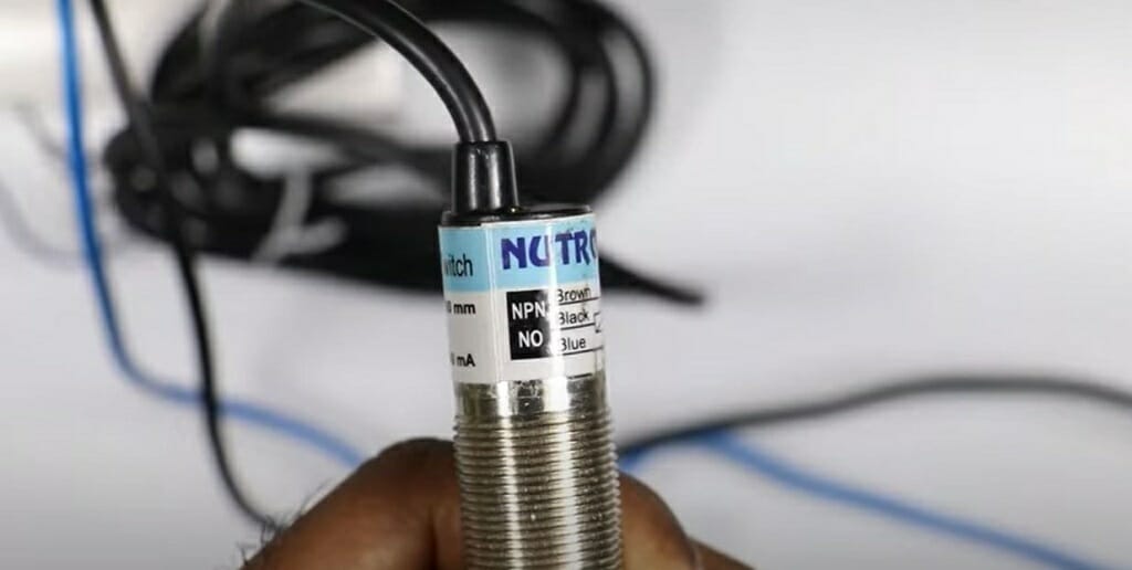
There are two types of sensors; NPN and PNP. PNP sensors operate on + voltage, and NPN sensors operate on – voltage. You’ll better understand this after I explain this circuit’s SMPS and NPN sensor connection.
How to Connect?
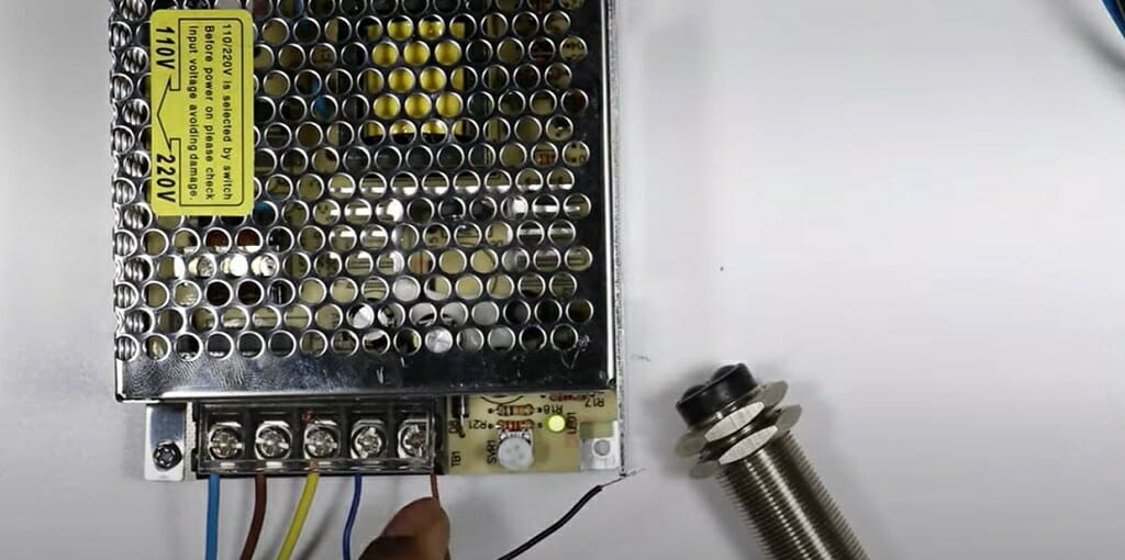
First, connect your home’s hot and neutral wires (blue and brown) to the SMPS. And don’t forget to connect the ground wire (green) to the SMPS too. Now SMPS is properly connected to your home’s AC power supply. Next, connect the sensor’s brown and blue wires to the SMPS’s V+ and V- terminals. Remember that because this is an NPN sensor, the brown wire is the positive connection, and the blue wire is the negative connection.
Tip: NPN sensors often come with three wires; blue, brown, and black. The black wire handles the output command.
Step 6 – Connect the Black Wire to the Terminal Box
I’m using a small terminal box to provide multiple output connections from one input connection for this process.
As shown in the above image, connect the sensor’s black wire to the terminal box.
Step 7 – Connect the Terminal Box to the SSR
After connecting the sensor to the terminal box, you can connect the SSR and the terminal box. To do that, take a black wire and establish the connection between the SSR and the terminal box.
As I mentioned earlier, I use an NPN sensor which means the output is negative. Hence, the black wire should connect with the SSR’s terminals 4. Terminal 4 is the negative connection, and Terminal 3 is the positive connection.
What to Do If You Are Using a PNP Sensor?
However, when using a PNP sensor, the output is positive. Hence, you should connect the black wire to terminal 3.
Also, the PNP sensor and the SMPS connection might vary compared to the NPN sensor.
Step 8 – Connect the SMPS and SSR
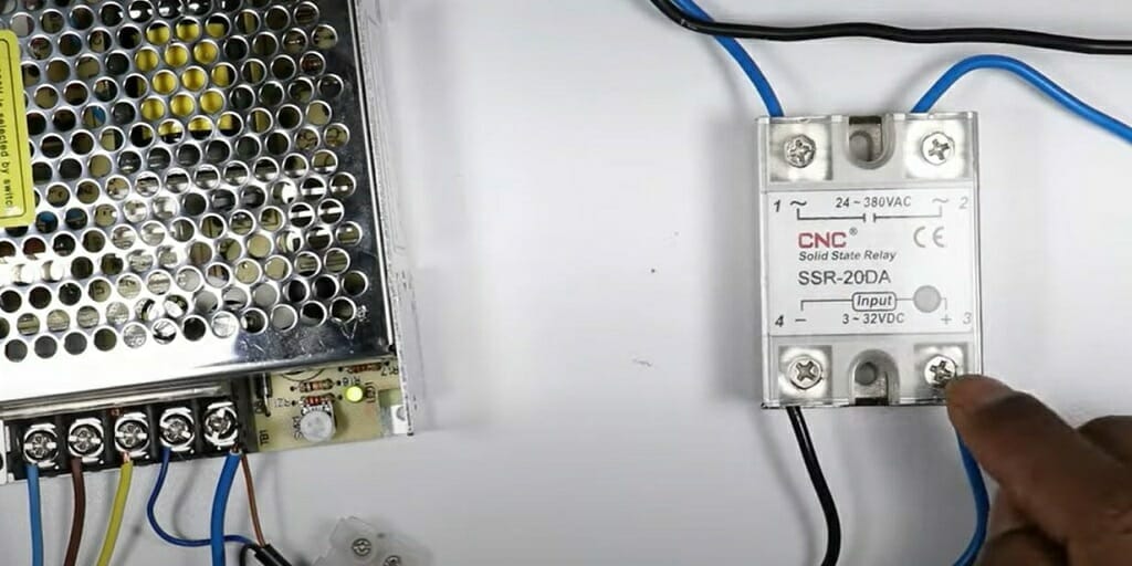
If you have come this far, you are almost done with this automatic light bulb circuit. You only have to connect the SMPS V+ terminal to the SSR’s terminal 3. I use a black wire (check the image) for this.
Step 9 – Test the Automatic Light Bulb
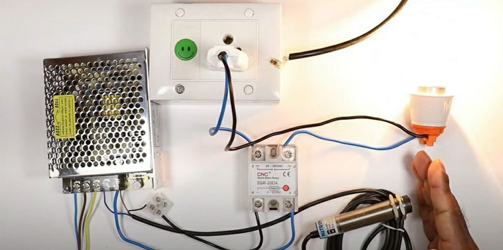
The sole purpose of this process is to make an automatic light bulb which on/off upon detection of any movement. So, it’s time to test our circuit.
Move your hand toward the NPN sensor. If the circuit is successfully wired, the bulb will turn on automatically. And when you take off your hand, the bulb will turn off itself.
However, if you cannot get a successful result, go through the above nine-step guide again. You might have wired the circuit incorrectly.
For a better understanding, check the video if you have any doubts.
How to Choose a Perfect SSR for Your Circuit?
Choosing a proper and suitable SSR is important for any application. For instance, you might need an SSR for temperature control or one for a simple circuit such as the above demonstration. Either way, choosing a perfect SSR goes a long way in deciding the success and failure of your application. Here are some factors you should consider while choosing a solid-state relay.
AC or DC
First, decide whether you need an AC SSR or DC SSR. AC SSRs take an AC input signal and give you a DC output signal.
On the other hand, DC SSRs input a DC input signal and release an AC output signal. As you already know, we used a DC solid-state relay for the above operation since the input signal is DC.
Apart from the above two types, you can find two more different SSR types; AC to AC and DC to DC.
Note: Using a DC SSR instead of the AC SSR won’t give you any results in the above demonstration. , the circuit will not work at all.
Voltage
The second thing you should pay attention to is the SSR voltage. Most SSRs in the market are designed to handle anything from 3 to 32 VDC. Hence, you can supply the input voltage to the SSR without concern. However, remember to buy an SSR which can handle 25% of the rated voltage than the circuit supply voltage. It will keep your circuit components and SSR safe.
Switching Current
The switching current is the load current, and you should always pay attention to it while buying SSR. Hence, cross-check the max load current of the SSR with the circuit’s inrush current.
All the above factors are vital for choosing the perfect solid-state relay for your circuit. Therefore, always check the specification first and make your choice.
SSR Wiring Diagram for Automatic Heater Control
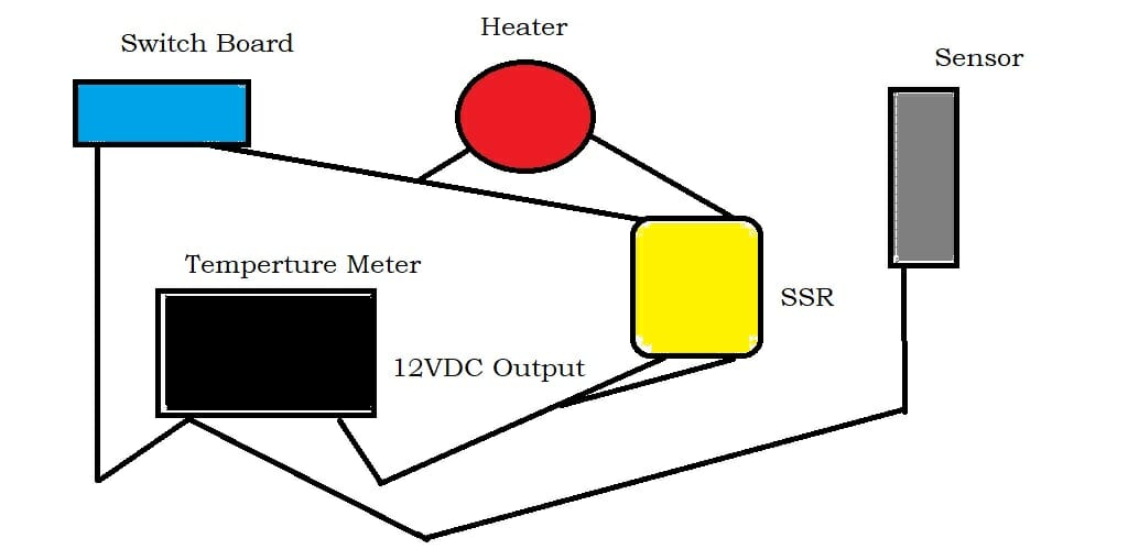
Using an SSR for an automatic heater control circuit is not a difficult task at all. You can apply the same process that you learn earlier for this circuit. However, there are a few changes in the circuit. Using a DC to AC solid-state relay for this circuit would be best. Check the above wiring diagram and complete the heater control circuit.
Video Reference
The Electrical Guy