9 min read
How to Wire a Light Switch and Outlet (Easy Steps)
You can wire a light switch and outlet together on the same circuit. I’ll show you how.
Combining the two can save you from wiring the two separately and may require less wire. It can be a convenient combination if the wiring and circuit breaker support the total current draw.
Quick Summary: If we lay a cable from the power source to the outlet first, then to the switch, and the light fitting, wire the light switch by connecting each of the two hot wires to its terminals. Then, connect the ground wire to the ground terminal, but let the neutral wires bypass the switch using a connector.
When connecting the outlet, connect the two black wires to the brass terminals, the two white wires to the silver terminals, and the ground wire to its ground terminal.
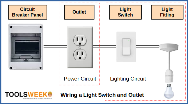
Refer to the block and circuit diagrams included in this article.
Wiring a Light Switch and Outlet
Considerations
A light switch and outlet should only be wired together if the wiring and circuit breaker support them. So it should not be done on a dedicated circuit.
Also, consider the total current draw of the connected appliances and light bulbs.
Assumptions
I assume the outlet and switch boxes and the light fitting are attached. So, the wiring to the light fitting is also done, and you are ready to do the wiring to connect the outlet and light switch.
Requirements
You will need the following tools and other materials:
| Tools | Materials | Instruments |
| Screwdriver Nose pliers Wire stripper | Cable Wire nuts Wire connectors Electrical tape | Outlet tester or similar |
Method
I’ve split the method for wiring a light switch and outlet into the light switch circuit and the outlet. We’ll focus on them separately.
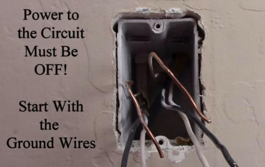
Before commencing the wiring, turn the circuit breaker OFF at the panel.

Turn the power off at the breaker panel before working on the wiring.
I’ve illustrated below how the parts will connect. We will wire the lighting circuit first, which will get power from the wires coming from the outlet, then on the outlet, which will get power from the panel.
Wires
The power source cable to the outlet is a regular 3-wire cable with one black (hot), one white (neutral), and one bare copper (ground) wire.
A 12/2 wire for the second cable from the outlet to the switch should be sufficient for a lighting circuit. You will also need an additional length of this cable from the switch to the light fitting.
Strip the ends of all the wires using a wire stripper, about half to 5/8 of an inch.
Wiring the Light Switch
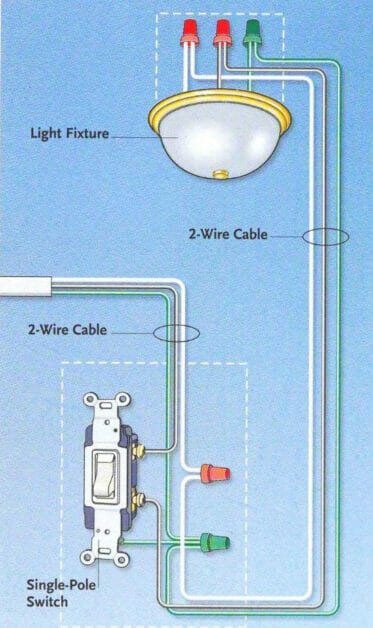
The wiring diagram for the lighting circuit is shown below. The incoming cable is from the outlet, and the outgoing one is to the light fitting.
Follow these three steps:
Step 1: Connect the Constantly Hot Wire
Connect the hot (black) wire in the cable from the outlet to the top terminal on the switch. This wire will be constantly hot (live) because it will connect directly to the power supply later without any switch in between.
Strictly, it doesn’t matter whether you connect it to the top or bottom terminal because the switch acts as a break and bridge in the hot wire going to the light fitting so it can be opened and closed. But, if you want the top position of the switch for turning the light off and the bottom for turning it on, then do it this way.
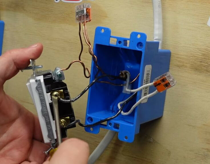
The screwdriver in the picture below is on this wire, which is different from the other hot wire going to the light fitting as a power carrier and will only be live when the switch is on.
Step 2: Connect the Secondary Hot Wire
Connect the secondary hot wire to the other/lower terminal on the switch. This is the black wire from the cable going to the light fitting. Since its functioning depends on the switch’s position, it’s not the constantly hot wire you already connected in Step 1.
Step 3: Connect the Neutral and Ground Wires
Connect the neutral (white) wires, then the bare copper (ground) ones, as shown above. Use wire connectors to connect them.
Note that the neutral (white) wires are NOT attached to the switch. They will bypass the switch by being connected directly.
However, you will need a small piece of bare copper wire for the ground connection to the switch. One end contains the main ground wires in the connector, and the other connects to the ground terminal on the switch with a green screw.
Wiring the Outlet
When wiring the outlet, you will again see two cables. The incoming one is the power supply cable coming from the panel, and the outgoing one is the light switch, which you‘ve already connected.
Step 1: Connect the Ground Wires
I suggest you start with the ground wires first, although it’s not strictly necessary to do it first.
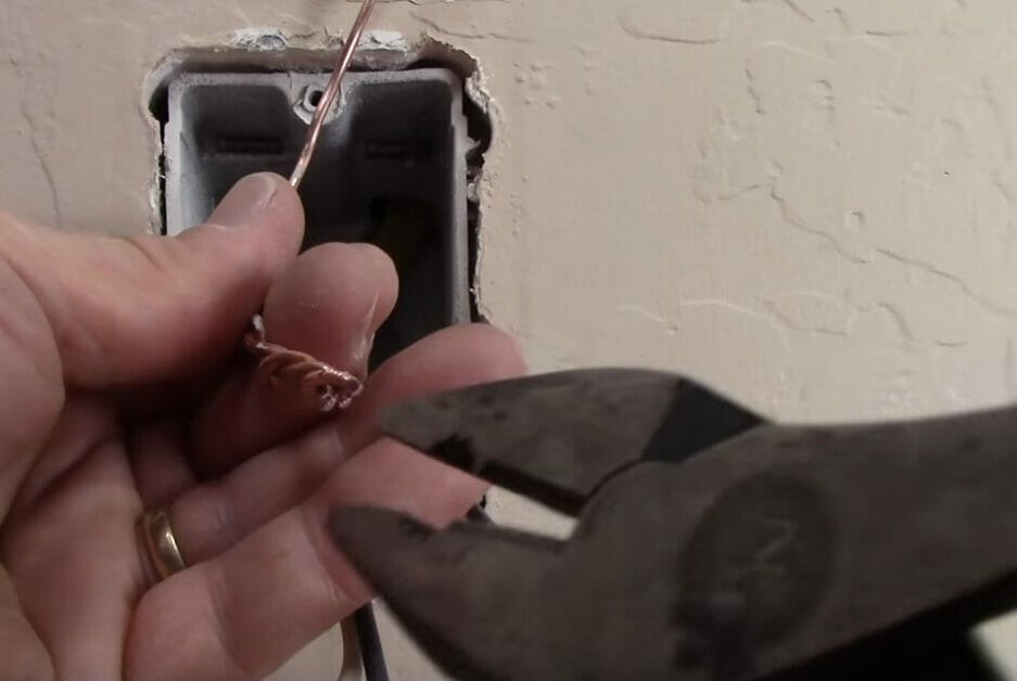
You will need another small bare copper wire to connect to the outlet.
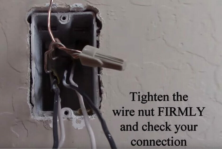
You can use a wire connector again as you did for the switch, but you can splice the three strands and connect them with a wire cap, as shown below, using pliers.
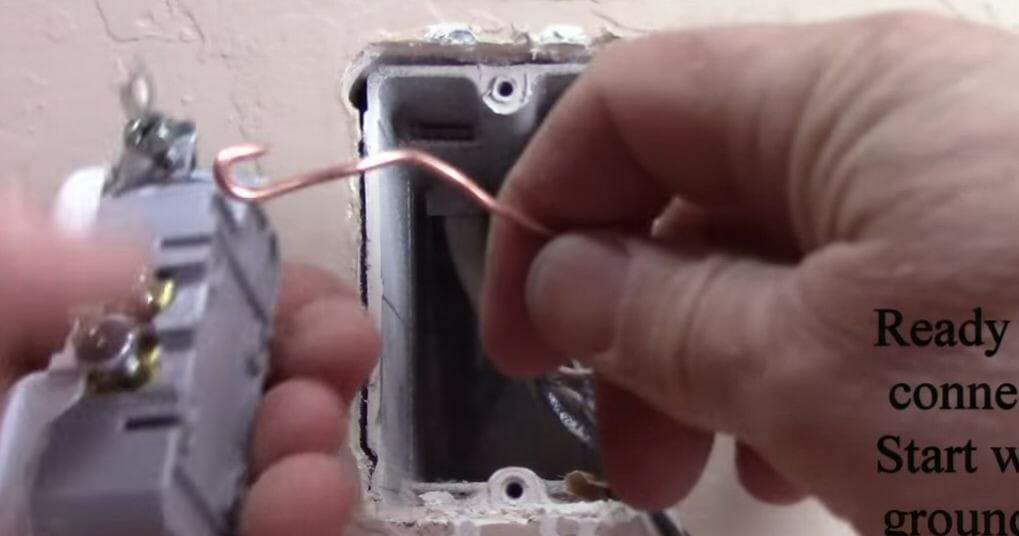
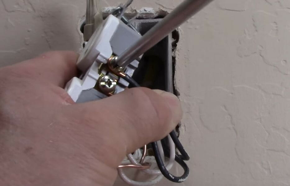
Step 2: Form Hooks
Form hooks at the end of the extra ground wire piece and all other wires (the two black and two white ones). See the example below for the hook on the small ground wire piece.
Step 3: Connect the Wires
Now, connect the wires sticking out as follows:
- Connect the two hot (black) wires to the terminals with brass screws. It doesn’t matter which one goes to which because a shunt connects the two hot terminals.
- Connect the two neutral (white) wires to the terminals with silver screws. Again it doesn’t matter which one goes to which silver terminal.
- Connect the ground wire to the terminal with a green screw.
Instead of connecting the hot and neutral wires directly to the outlet, you can use wire connectors as you did for the ground wires, but you will need small pieces of each to connect the connectors to the outlet’s terminals.
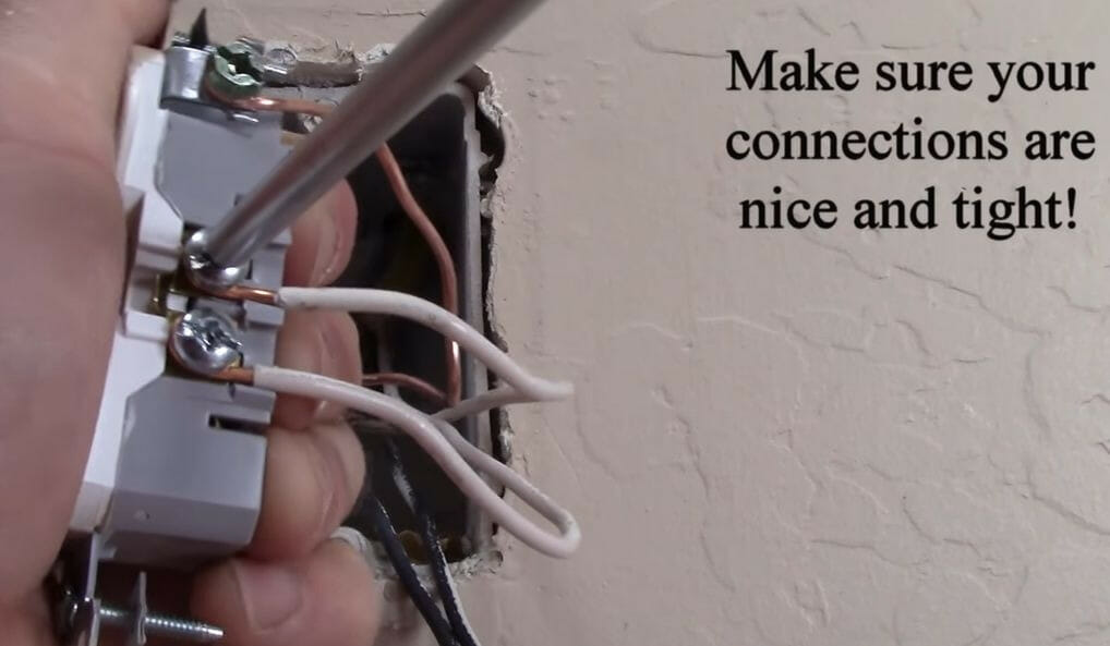
Ensure tight connections on all the outlet’s terminals and the wire connectors.
Step 4: Tuck the Wires Inside
The outlet is now wired so you can tuck all the wires inside the outlet’s box.
Step 5: Test the Circuit
Before we finish off by attaching the light switch and outlet, let’s test them safely.
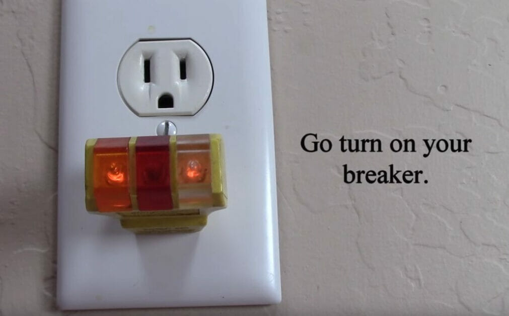
Turn on the breaker temporarily, and:
- Test the outlet using a plug tester, as shown below.
- Test the light switch by switching it on and off to see if the light comes on and goes off.
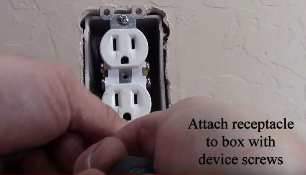
Step 6: Attach the Switch and Outlet
Remember to turn the breaker back OFF.
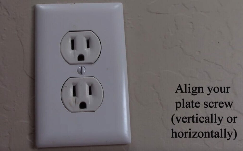
Attach the switch to the switch box and the outlet to the outlet’s box. Then attach the faceplates to each of them.
Only then, turn the breaker ON.
References
Creative Homeowner. The ultimate guide to wiring: complete home projects. 6th edition. Creative Homeowner. 2007
Video References:
HandyDadTV
Terry Peterman