10 min read
How to Wire a Receptacle (12 Steps)
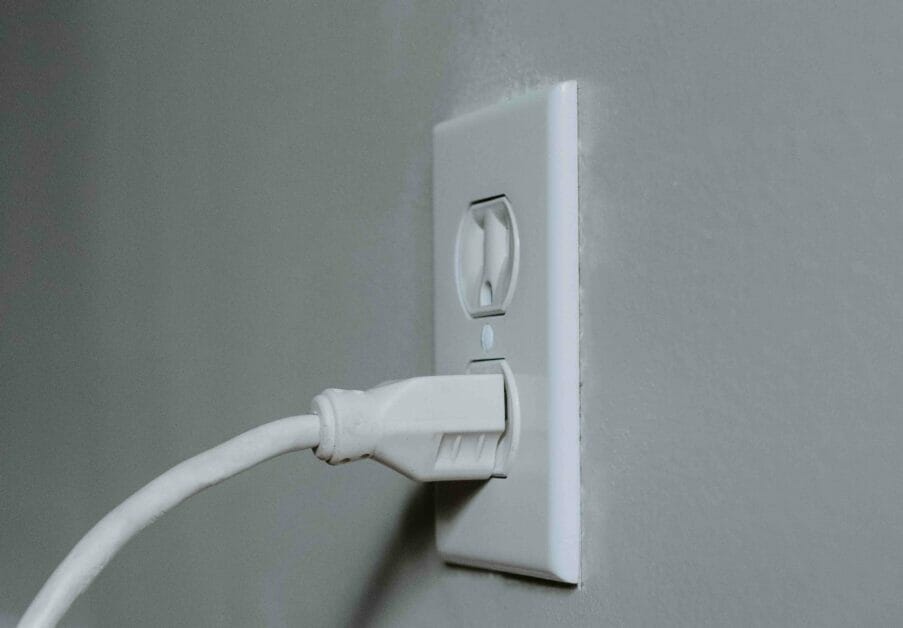
This is a straightforward yet detailed and illustrated guide to wiring a receptacle, suitable for beginners.
Quick Summary: When wiring a (regular) receptacle, connect the wires as follows:
- Connect the bare copper wire to the ground terminal marked ‘GRD’ or ‘Ground’ with a green screw.
- Connect the white wire to the neutral terminal marked ‘Neutral’ or ‘White’ with a silver screw.
- Connect the black wire to the hot terminal marked ‘Hot’ or ‘Black’ with a brass screw.
Whether you have one or two cables coming through or prefer using wire caps and connectors, they’re all covered in this easy-to-follow guide to wiring a receptacle.
Before You Start
Requirements
Gather these tools and other equipment for this project to wire a receptacle:
- Main item: the receptacle (aka outlet)
- Tools: screwdriver, pliers, wire stripper, plug tester
- Other items: wire nuts (at least one for the ground wire)
- If you have two cables and are applying the alternative option: small pieces of one black and one white wire
Precautions
As mentioned in Step 1, you must turn the power off at the main panel before wiring the receptacle. Switch the circuit breaker controlling the circuit you will work on to the OFF position.
Assumptions
I assume the box is already attached to the wall, the right cables are inserted and sticking out, and the receptacle you have ready is a regular (non-GFCI/AFCI) one. This guide describes how to proceed by wiring the cables to the receptacle.
Cabling
Note that the illustrations show two sets of cables.
One cable is from the power supply, i.e., from where power enters the outlet box. The other cable is not necessary if it’s a dedicated circuit or if the outlet you’re going to wire is at the end of the circuit. You will only see one cable coming through in that case. It’s only required if the outlet will supply power to another outlet down the line as a power carrier.
So, if you have only one cable coming through, you won’t need to splice wires or use wire caps or connectors. Simply connect the wires (after forming hooks at their ends) directly to the terminals on the receptacle.
Wiring a Receptacle
We will follow these 12 steps to wire a receptacle:
- Step 1: Turn the Power Off
- Step 2: Splice the Ground Wires
- Step 3: Strip the Wires
- Step 4: Form Hooks
- Step 5: Connect the Ground Wire
- Step 6: Connect the Neutral Wires
- Step 7: Connect the Hot Wires
- Step 8: Tuck the Wires
- Step 9: Attach the Receptacle
- Step 10: Attach the Faceplate
- Step 11: Turn On the Breaker
- Step 12: Test the Power
Step 1 is an essential precaution. Steps 2-8 describe the actual wiring procedure, steps 9-11 are for securing the fixture and switching the power back on, and Step 12 is recommended for testing the outlet before using it.
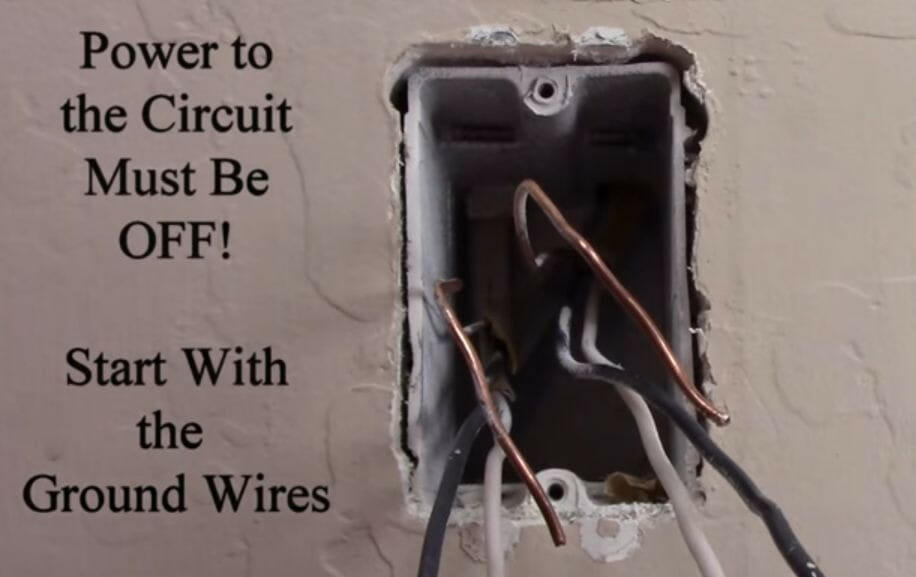
Step 1: Turn the Power Off
The power to the circuit you will work on must be switched off.
If you’re a beginner, ensure you can positively identify the wires sticking out of the box. Refer to the table below, according to the US system for domestic, single-phase AC circuits.
| Wires | Type |
| Black wires | Hot (or live) |
| White wires | Neutral |
| Bare copper wires | Ground (or earth) |
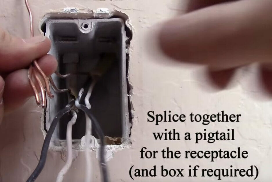
Step 2: Splice the Ground Wires
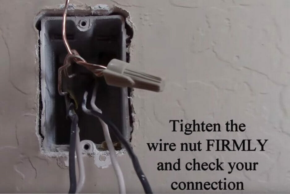
Splice the ground (bare copper) wires together along with an extra, small piece using pliers.
By starting with the ground wires, we can clear them out of the way to work on the others.
Cut the tip off the end of the spliced ground wires with the pliers.
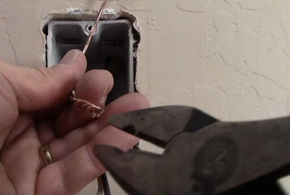
Attach a wire cap to the end and tighten it firmly by twisting again.
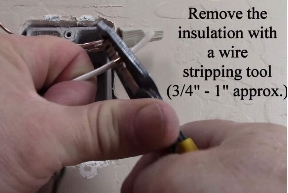
Step 3: Strip the Wires
Strip the ends of the hot (black) and neutral (white) wires using a wire stripper.
Remove approximately half to one inch of the insulation layer.
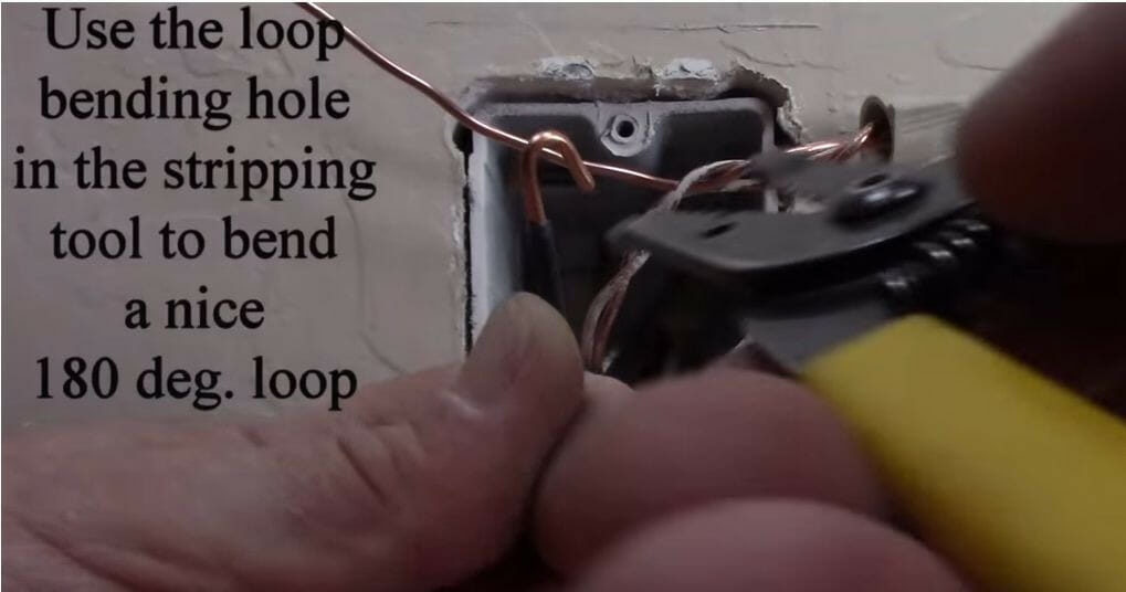
Step 4: Form Hooks
Form hooks at the end of each of the hot and neutral wires.
This is only necessary if you connect the wires directly to the outlet instead of wire connectors (see the alternative method described in Step 6).
Some wire strippers have a loop bending hole to insert a wire end into which you bend 180° to form a hook. Form a hook at the end of the third piece of ground wire.
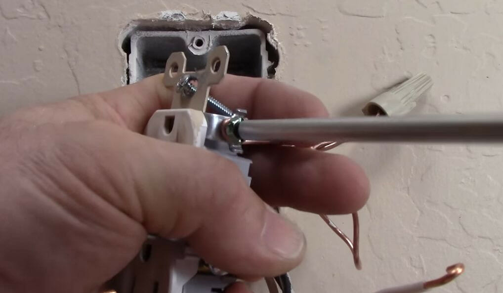
Step 5: Connect the Ground Wire
Connect the ground wire (the third piece extending from the pigtail) to the receptacle’s ground terminal with a green screw. Always put the loop around the terminal screw in a clockwise direction.
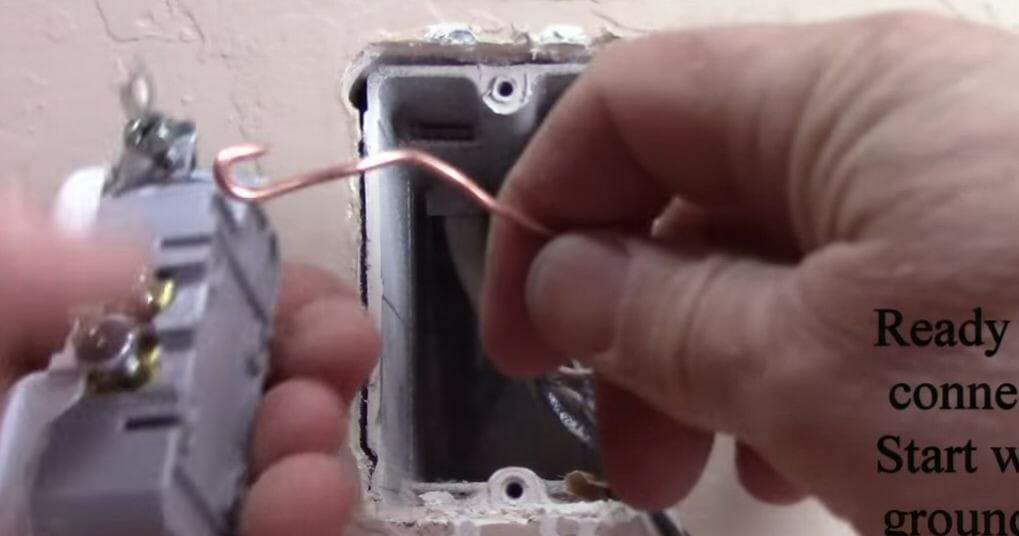
Ensure the green screw is tight.
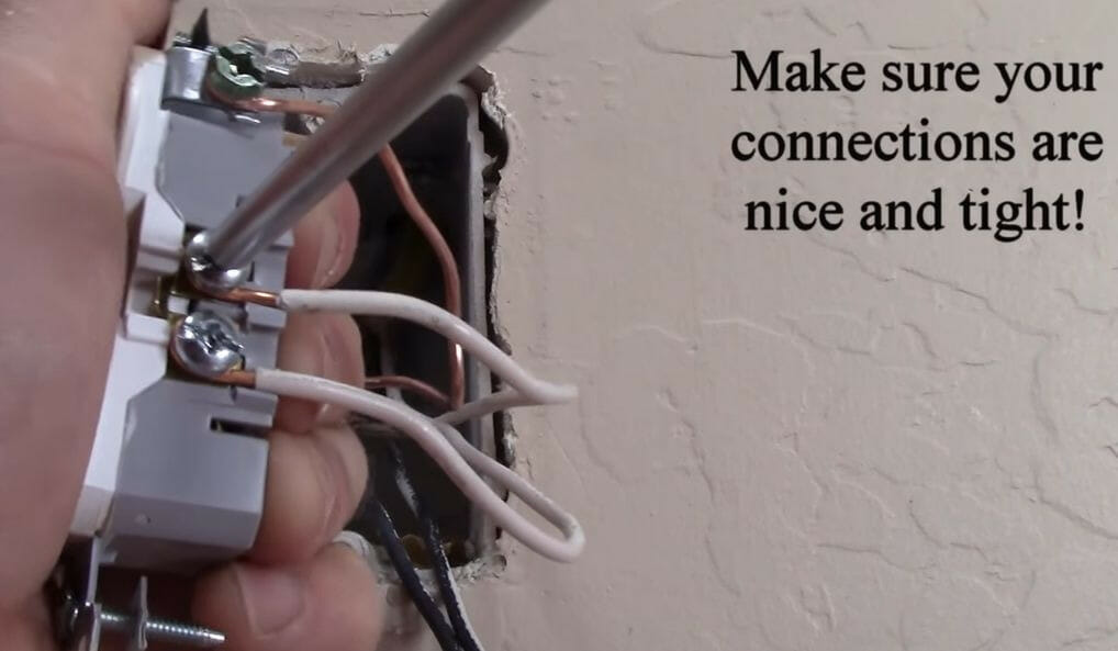
Step 6: Connect the Neutral Wires
Connect the neutral (white) wires to the silver screws.
It doesn’t matter which white wire connects to which silver terminal because a shunt connects both terminals. Ensure the connections are tight.
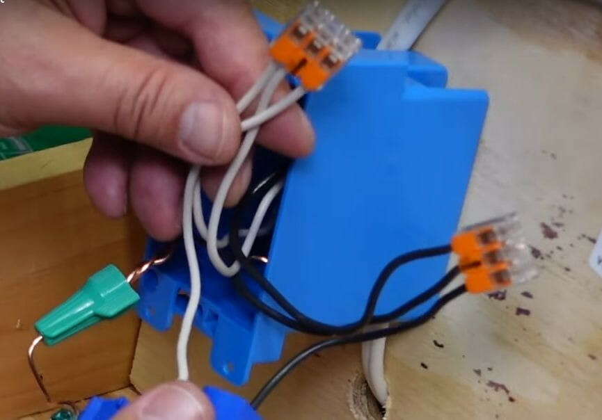
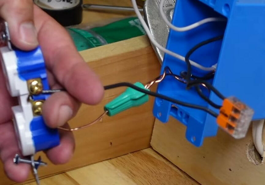
An alternative is using a wire connector if you have more than one cable coming through. You won’t need to form hooks, either. Simply insert the wire ends into the connector, plus an additional small piece of wire, which will require a hooked end (see the picture below). Close the connector and connect that small piece to the outlet (either of the two neutral terminals).
Step 7: Connect the Hot Wires
Connect the hot (black) wires to the brass screws. Ensure the connections are tight.
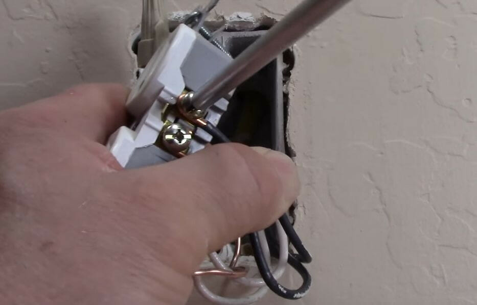
The same alternative option using a wire connector described in the previous step for the white wires can be applied to the black wires.
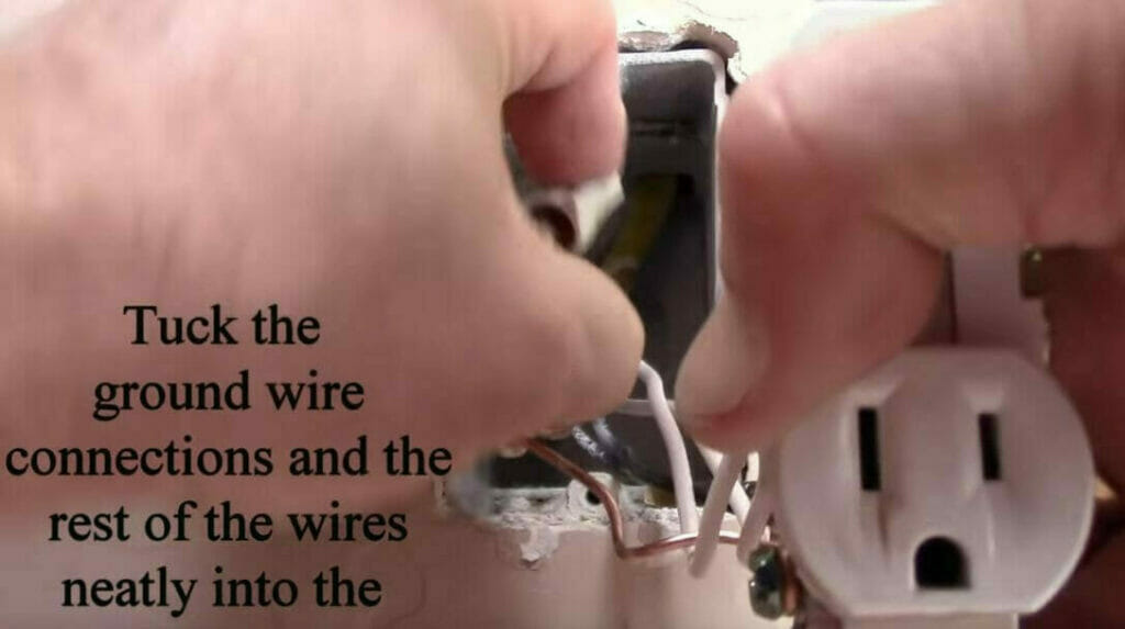
Step 8: Tuck the Wires
Tuck all the wires neatly inside the outlet’s box.
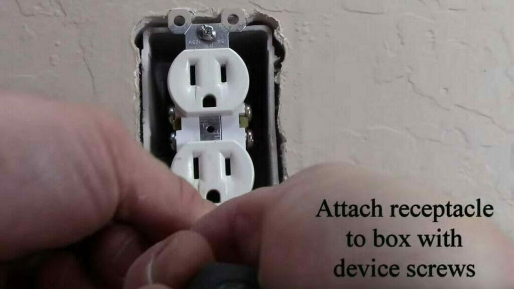
Step 9: Attach the Receptacle
Attach the receptacle to the outlet’s box with the device screws. Ensure the screws are tight and the receptacle is attached securely. The receptacle should automatically be straight if the box is straight because the holes for the device screws are vertically aligned.
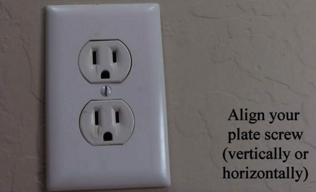
Step 10: Attach the Faceplate
Attach the faceplate and screw it on. If possible, try to finish by aligning the groove in the screw’s head vertically or horizontally.
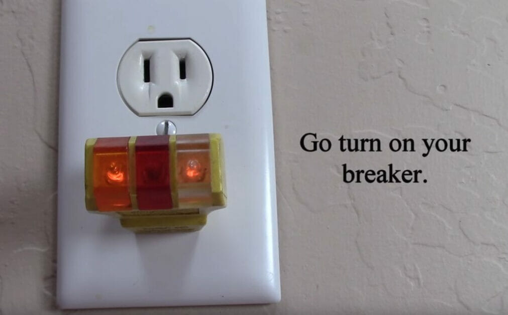
Step 11: Turn On the Breaker
Now that the receptacle is wired and attached, turning the breaker back on is safe.
Step 12: Test the Power
It’s a good idea to test the outlet before making it ready.
Use a light or plug tester (as shown in Step 11). The color and sequence of the lights will indicate whether the circuit is okay. Hopefully, it will reassure you that you wired the receptacle correctly the first time.
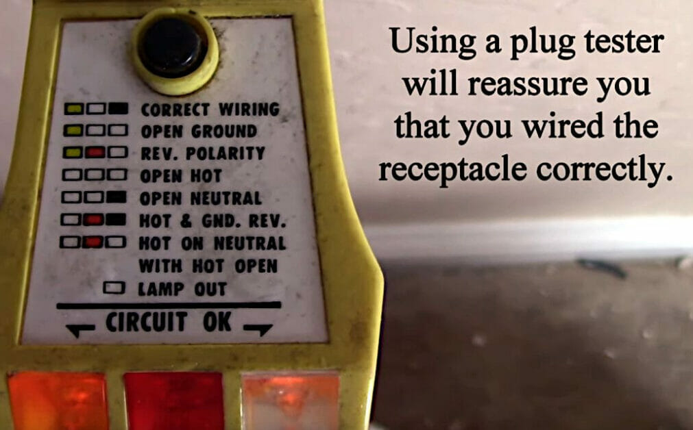
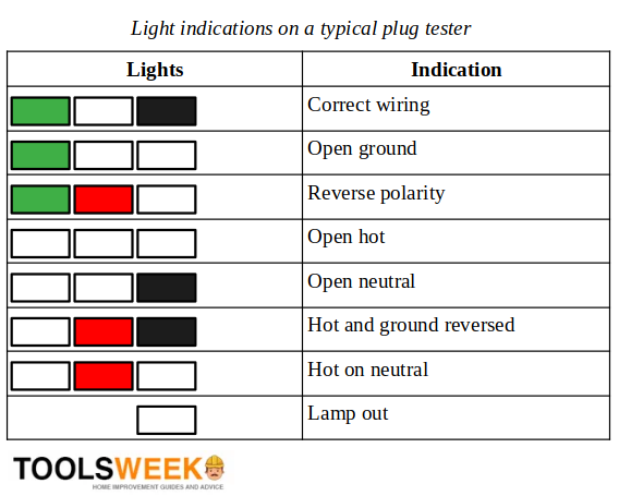
Here’s a guide to what the lights indicate:
References
Video References
HandyDadTV
Terry Peterman