6 min read
How to Convert Single Phase to Three Phase Circuit Diagram
This article is about how we can convert a single-phase circuit to a three-phase one, with an illustration of the circuit diagram.
Warning: Experimenting with electricity can be very dangerous and even fatal. Using the information on this page, you acknowledge that you are aware of this risk and will take all necessary precautions if you decide to follow any practical measures.
I will teach you what you need to know about the two types of electricity supplies, the reasons why you might want to do this conversion, the types of phase converters that you can use, show you a circuit diagram for a three-phase converter and will give you more related information.
You Can Use or Make Four Types of Converters to Get to A Three Phase Circuit:
- A Static Converter,
- A Rotary Phase Converter,
- A Variable Frequency Drive and
- A Digital Phase Converter.
Their circuits typically make use of capacitors, rectifiers, and an inverter. Some key advantages of a three-phase power supply are constant power delivery, less use of copper, and the ability to use smaller but more powerful electrical motors, as mostly used in industry.
What are Single and Three-Phase Circuits?
A single-phase electricity supply is most common in residential homes and non-industrial places, whereas a three-phase system is mostly used in industry.
A single-phase is sufficient when the loads are mostly lighting and heating appliances. Still, a three-phase connection is necessary when many electric motors and other heavy loads are continuously used. Another difference is in the magnetic field produced around them. A three-phase supply produces a revolving magnetic field, which is not the case with a single-phase one.
Three-phase systems are costlier due to the generators, extra transmission lines, and loads required.
Why You Would Need to Convert
There are two solutions for operating three-phase equipment with only a single-phase connection.
Your options are to either have your supply converted, which can be costly, or to arrange the conversion internally on your premises.
If a three-phase service is unavailable in your area, you only have the latter option, so continue reading to find out how to do this.
There are more incentives to use a three-phase system:
- You get more power for the equipment you use on it.
- Less copper (or aluminum) is used to provide this power.
- The power delivery is constant. It doesn’t pulsate, as in a single-phase system.
- It allows you to use smaller-sized motors due to greater efficiency.
- It gives better power factor regulation.
Phase Converters
Converters can allow you to use three-phase equipment in places serviced by single-phase connections without changing your supply.
A few different types of converters can help you convert single-phase to three-phase circuits. They are static converters, rotary phase converters, variable frequency drives (VFDs), and digital phase converters (DPCs).
Static Converters
A static converter is a simple type of converter.
It relies on the fact that a three-phase motor can stay running on a regular single-phase supply once started. It uses capacitors as a temporary substitute for one phase.
However, this converter is inefficient and will reduce the motor’s lifespan.
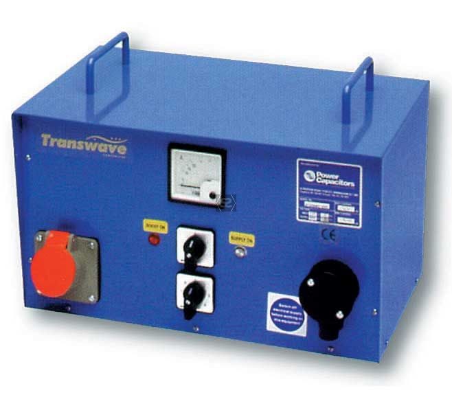
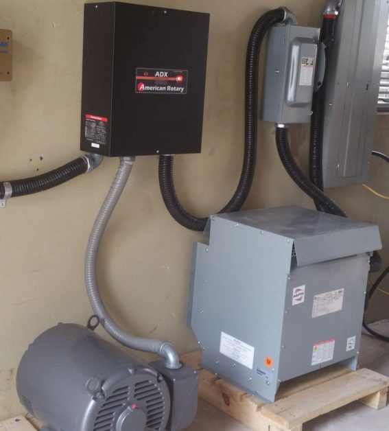
Rotary Phase Converters
A more advanced type, a rotary phase converter, is an independent generator and a substitute three-phase motor. Once in operation, it generates power to work like a three-phase system without turning any moving parts.
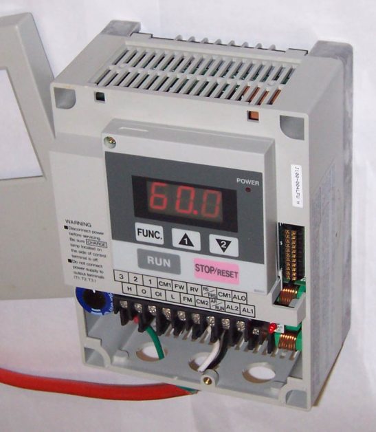
Variable Frequency Drives
A variable frequency drive (VFD) is designed for greater motor and constant pressure control.
It generates AC power at any set frequency, replicating a typical three-phase motor. But it is not suitable for electronics. It is only used for running motor loads. It can also be used for pivot applications.
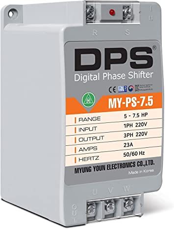
Digital Phase Converters
A digital phase converter (DPC) is ideal when you want clean three-phase output, you need to power multiple loads at different times, and if the equipment has internal VFDs.
Unlike a VFD, it can be used for running electronics and is not limited to motor loads.
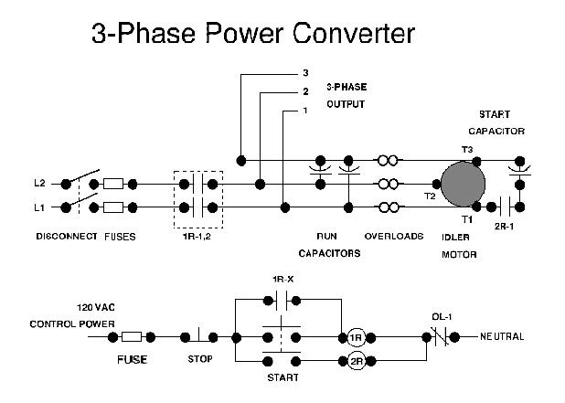
The Circuit Diagram
When you use three-phase power, a digital signal processor (DSP) creates a third voltage to provide a balanced supply.
Three main components are involved in the process: capacitors, rectifiers, and an inverter.
There are two common ways of achieving this. You can connect a single-phase load between one phase and the neutral connection for Y-connected systems. But the connection between a phase and center tapped neutral on one leg is made for Delta systems. This is the most common method in the United States.
The result is a circuit that will look somewhat like the one shown below.
Constant Power
I mentioned earlier that continuous power delivery is a key advantage of a three-phase supply.
Only the power is constant. Voltage and current are not constant, so we call it ‘alternative current’ (AC). The relationship, in this case, between power (in watts), voltage (in volts), and electrical resistance (in ohms) are as follows:

Due to the squaring of the voltage, negative values for it also contribute to the power (P), and the total power is the sum of the three power values.
Another relevant formula is the Three-Phase Power Formula:
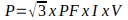
PF is the power factor, usually between 0.85 and 1.
Wrapping Up
You can use or make a converter to convert a single-phase to a three-phase circuit. It will give you the advantages of three-phase circuits, such as more constant power, greater efficiency, and the ability to use smaller but more powerful electrical motors. Typical converters available are static converters, rotary phase converters, variable frequency drives, and digital phase converters. I also presented a circuit diagram of one such type and gave you two key formulas that apply to three-phase circuits.