9 min read
Load Wire vs Line Wire (What’s the Difference?)
Hey there, DIY enthusiasts and home improvement heroes! Ever find yourself standing in front of your electrical panel, scratching your head, trying to figure out the maze of wires in front of you?
Today, we’re diving into a topic that might seem like it’s just about colors and labels, but trust me, it’s the heartbeat of any electrical project: the difference between load wire and line wire.
You can differentiate a load wire and line wire in a circuit by considering the following features:
- Wire placement
- Wire codes
- Wire size
- The measurement of voltage (V) and current (Amps)
So, grab your tool belt, and let’s get ready to shed some light on the load wire versus line wire conundrum. It’s not just about keeping your circuits happy; it’s about keeping you, your family, and your home safe.
The Basics of Load and Line Electrical Wires
Let’s break it down and make sense of the whole line and load wire saga, something that’s super crucial when you’re diving into the world of electrical work in your home.
Line Wire
These wires are the first point of contact for electricity directly from your power source, be it the grid, a generator, or solar panels. Think of them as the front door to your home’s electrical system, welcoming all that power.
Line wires are typically black or red and are hot, carrying the live electrical current. Identifying these wires is crucial when working on an electrical project because they bring in the juice.
Always treat them respectfully and cautiously, ensuring all safety measures are in place. We want a home makeover, not a hair-raising shock!
Load Wire
Now, let’s talk about the load wires. These wires take the electricity from your main entrance (the line wires) and distribute it to your various appliances, outlets, and fixtures. You can think of load wires as delivery trucks, taking electricity where it needs to go inside your home.
Load wires are often connected to the output terminals of switches or circuit breakers. They carry power to the load, anything from your fridge to your fancy lighting fixtures. These wires are usually white or grey, but check because wiring colors vary.
Remember, every wire has its role, and understanding these roles is your secret weapon in mastering the electrical mysteries of your castle.
RELATED Is Line or Load the Hot Wire?
Load vs. Line Wires
Let’s dive straight into the nuts and bolts of distinguishing between line and load wires, a crucial step to ensure your electrical projects are safe and up to snuff.
Video | Upgrade Your Home DIY
Understanding these differences is key to avoiding any mix-ups leading to electrical mishaps.
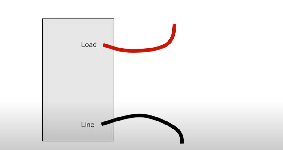
1. Wire Placement
Line Wires: These are your electrical system’s first responders. In terms of placement, line wires are connected directly to your circuit breaker or fuse box. From there, they travel to switches or outlets, providing the initial power entry point.
Load Wires: Following the storyline, load wires take their cue from the line wires. After the switch, load wires reach the actual electrical devices or fixtures (the load). This placement ensures that electricity is safely distributed to where needed.
2. Color Codes
Line Wires: Line wires typically wear black or red costumes. These colors signify that they’re hot and carrying power directly from the source. It’s their way of saying, “I’m alive; be careful around me.”
Load Wires: Load wires, on the other hand, might follow a different color scheme. In many systems, they’re also black, which can sometimes make it a bit of a plot twist when distinguishing them from line wires. However, the key is remembering their role in the electrical narrative—delivering power to the load.
3. Wire Size
Line and Load Wires: The size of both line and load wires is determined by the amount of current (measured in amperes or amps) they need to carry and the length of the wire.
The wire gauge (AWG) is crucial here; the higher the current or the longer the distance, the thicker the wire must be to safely carry the electricity without overheating. It’s like choosing the right size costume for performers to ensure they can move freely and safely.
4. Measurement of Power Features
Line Wires: These wires are all about bringing in the power, so the measurement of power features here includes voltage level (typically 120V or 240V in residential settings) and current capacity. The circuit breaker they’re connected to also plays a critical role in defining the maximum current they can carry.
Load Wires: For load wires, the measurement of power features revolves around the requirements of the electrical devices they’re powering. Each device will have its own voltage and current requirements, and the load wires must match these specifications to ensure efficient and safe operation.
Understanding these aspects of line and load wires not only helps in proper electrical installation and maintenance but also ensures the safety and efficiency of your electrical system.
Electrifying Troubleshooting Tips: Navigating Common Electrical Issues
Let’s dive into some electrifying troubleshooting tips as if a charismatic, enthusiastic home improvement guru is guiding you through the maze of wires in your home.
Imagine rolling up your sleeves and getting ready to tackle those pesky electrical gremlins with a can-do attitude and a smile. Here’s how we’re going to break it down:
| Problem | Troubleshooting Tip |
|---|---|
| The circuit is not powering up | Verify the connections of line and load wires. The line wire should be connected to the terminal marked “LINE.” If they are connected incorrectly, the circuit will not function. |
| Flickering or dim lights | Check the wire connections for tightness. Loose connections can cause inconsistent lighting. Ensure all connections are secure. |
| Tripping breakers | Assess the total wattage of devices on the circuit against the breaker’s rating. If the wattage exceeds the rating, redistribute the load or upgrade the breaker. |
| Outlet not working | Use a voltage tester to check for power in the line wire at the outlet. Inspect the electrical panel for tripped breakers or loose connections if there is no power. |
| Buzzing sounds from outlets or switches | Inspect for loose connections or faulty devices. Tighten any loose connections. If the issue persists, replace the faulty outlet or switch. |
Always prioritize safety when dealing with electrical issues. If the problem persists or you are unsure about working with electricity, consult a professional electrician.
Frequently Asked Questions
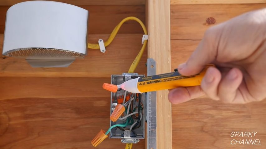
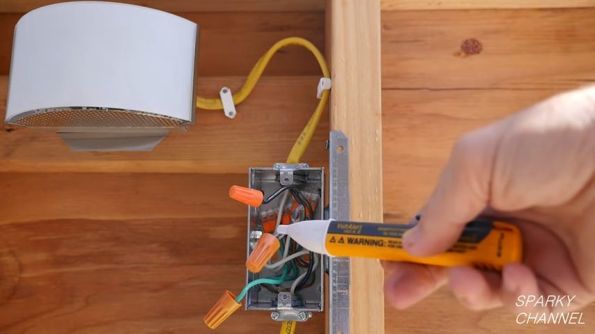
- How Do I Safely Test for Line/Load Wires?
- Use a non-contact voltage tester around the suspected line/load wires to detect any electrical charge. For a more thorough check, a multimeter set to measure voltage can confirm whether you’ve correctly identified the line wire.
- What Should I Do If I’m Unsure About My Wiring?
- When uncertainty strikes, pause and seek professional advice. Electrical systems are not forgiving of mistakes. A licensed electrician can provide clarity, ensuring your home’s electrical safety and functionality. It’s better to invest in professional services than to risk potential hazards.
- How Can I Recognize Signs of Improper Wiring?
- Signs include flickering lights, unresponsive outlets, buzzing sounds from switches or outlets, discolored wall plates, and frequent breaker trips. These symptoms could indicate improper wiring, overloading, or faulty electrical components. Immediate professional assessment is recommended to prevent more serious issues.
- Is It Important To Know The Difference Between Load And Line Wires?
- Absolutely! Correctly identifying load and line wires is critical for any electrical work. This knowledge prevents potential hazards and ensures electrical circuits function safely and efficiently. It’s a fundamental aspect of electrical safety and proper system operation.
- Can Reversing Line and Load Wires Cause Damage?
- Yes, reversing these wires can lead to electrical hazards, including shock and fire risks. Certain devices, especially those requiring a specific power flow direction, may malfunction or not work at all, posing serious safety concerns.
- Why Are Color Codes Important in Electrical Wiring?
- Color codes standardize wiring practices, making it easier to identify the purpose of each wire. They help in safely installing, troubleshooting, and repairing electrical circuits. Knowing your local color code standards is crucial for any electrical project.
- What Are The Best Tools For Identifying Line And Load Wires?
- A non-contact voltage tester and a digital multimeter are essential. These tools help you safely identify live wires without direct contact. For more in-depth analysis, a clamp meter can measure the current flow, helping distinguish between line and load wires based on the load they carry.
- How Often Should I Check My Home’s Electrical Wiring?
- Regular inspections are key. It’s recommended to have a professional electrician check your home’s wiring at least every 10 years. Consider more frequent inspections for older homes or if you’re experiencing any warning signs mentioned earlier.
Resources
Organizations:
- National Electrical Manufacturers Association (NEMA) –https://www.nema.org/
- International Electrotechnical Commission (IEC) –https://www.iec.ch/homepage
- Institute of Electrical and Electronics Engineers (IEEE) –https://www.ieee.org/
- Occupational Safety and Health Administration (OSHA) –https://www.osha.gov/
Books:
- “Wiring a House” by Rex Cauldwell – https://www.academia.edu/42273192/Rex_Cauldwell_4th_Edition_Wiring_a_House
- “Electrical Wiring Residential” by Ray C. Mullin and Phil Simmons – https://books.google.com.ph/books/about/Electrical_Wiring_Residential.html?id=vu_FDwAAQBAJ&redir_esc=y
- “The Complete Guide to Home Wiring” by Black & Decker – https://books.google.com.ph/books/about/The_Complete_Guide_to_Home_Wiring.html?id=caIfHk5H9JQC&redir_esc=y
Website Resources:
- This Old House – https://www.thisoldhouse.com/
- The Spruce – https://www.thespruce.com/
- Electrical Safety Foundation International (ESFI) –https://www.esfi.org/
Video References:
Sparky Channel
Upgrade Your Home DIY