6 min read
How to Test a Transformer without Power (5 Steps)
In this article, I’ll teach you how to test a transformer without power using the most widely used electrician-approved tests.
Quick Summary: To test a transformer without power:
- Set the multimeter to resistance settings.
- Identify the primary and secondary windings correctly.
- Test 1 – Check the resistance between primary terminals and secondary terminals.
- Test 2 – Check the resistance between the primary terminals and the transformer’s core.
- Test 3 – Check the resistance between the secondary terminals and the transformer’s core.
- Your transformer works properly if all three tests indicate an open circuit (infinite resistance).
Follow the below step-by-step guide for a detailed explanation.
5-Step Guide on How to Test a Transformer without Power
For these tests, you’ll need a few things. So, gather them before getting started.
Things You’ll Need
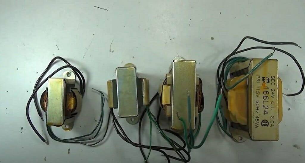
- A new transformer
- Digital Multimeter
- Two alligator clips (red and black)
- Something to take notes on
Step 1 – Set the Multimeter to Resistance Settings
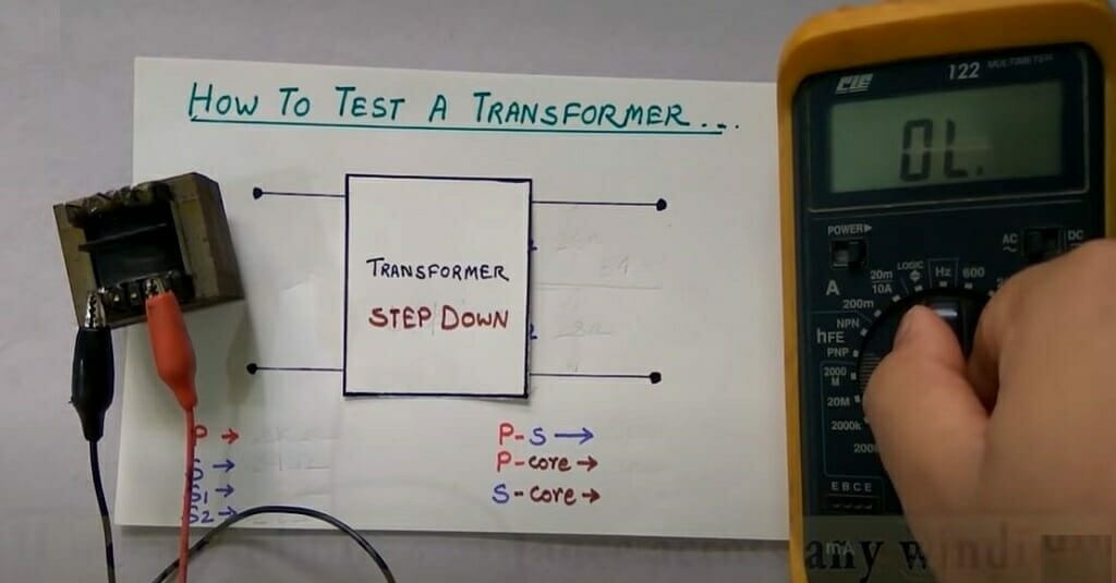
First and foremost, take the multimeter and set it to resistance mode. Connect the red and black jacks to the ohms and COM ports. Turn the dial to the resistance settings.
Quick Tip: Depending on the measured resistance, you might have to change the multimeter’s resistance range. Otherwise, you won’t get an accurate reading.
Step 2 – Identify the Primary and Secondary Windings
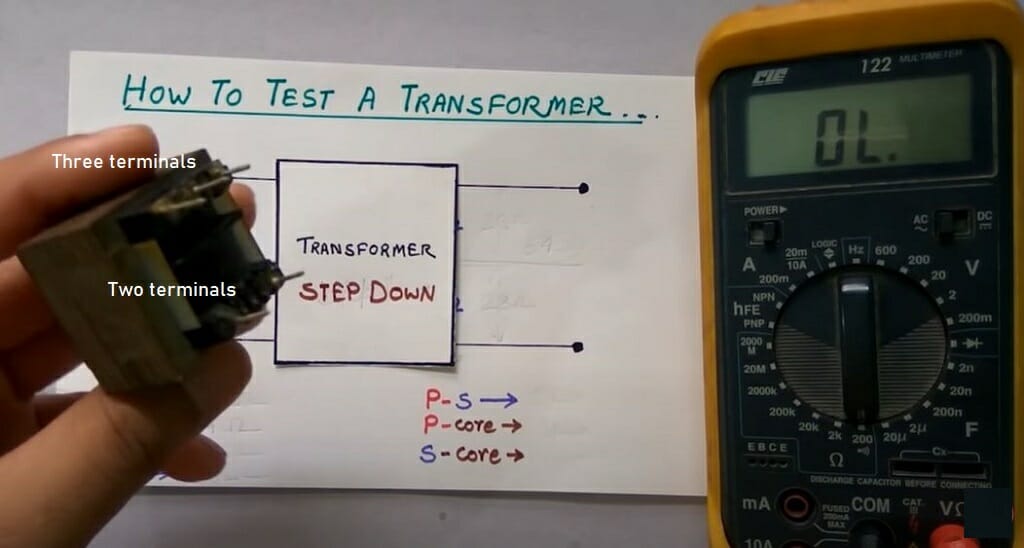
For this demonstration, I’m using a transformer that has a total of five terminals.
As you can see, three terminals are on the top and two on the bottom of the transformer. Some terminals belong to the primary winding, and some belong to the secondary winding. So, I cannot move forward without identifying the primary and secondary terminals.
Difference Between the Primary and Secondary Windings
Typically, the primary winding is capable of drawing power from the source. On the other hand, the secondary winding delivers energy to the load.
Quick Tip: In a transformer, the secondary current changes according to the primary current. Secondary winding creates the secondary current.
Most often, the winding that has two terminals is the primary winding. The winding that has three terminals is the secondary winding. So, the top winding (three terminals) is the secondary winding. The bottom one (two terminals) is the primary one.
Nevertheless, you can do a simple test to identify the primary and secondary windings.
- Turn the multimeter’s dial to 20K (resistance).
- Connect the two alligator clips to the multimeter probes.
- Check the resistance of the bottom two terminals.
- Note down the reading.
- Check the resistance of the top terminals (ignore the middle terminal).
- Note down the reading.
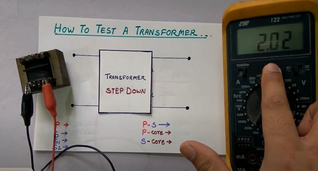
I got a 2.02KΩ reading for the bottom terminals.
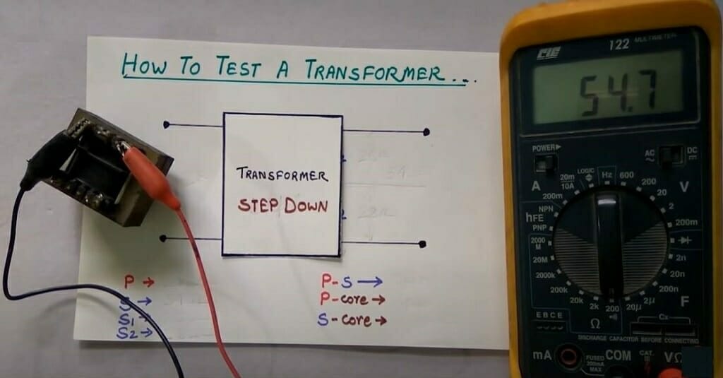
I got a 54.7Ω reading for the top terminals.
Important: You might have to change the resistance range if you get an infinite or decimal reading. For instance, I used a 20K range for the bottom terminals and a 200Ω range for the top terminals.
Quick Tip: The winding with higher resistance is the primary winding.
Therefore, the 2.02KΩ winding is the primary winding (bottom two terminals). The 54.7Ω winding is the secondary winding (top three terminals).
Step 3 – Test Primary and Secondary Terminals
Before Starting: After identifying the primary and secondary windings, you can begin testing.
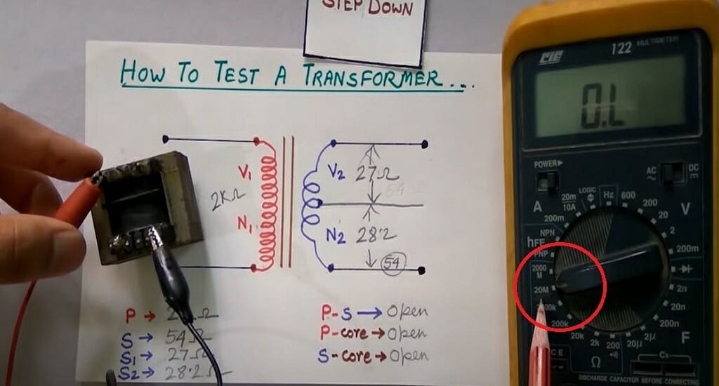
You can check for short-circuit situations by doing the three tests below. A short circuit in a transformer can damage the transformer permanently. Hence, in the below tests, I will check for short circuits.
The transformer works fine if the readings show an open circuit (infinite resistance). Also, carry out tests for both 200Ω and 20MΩ resistance ranges.
- Connect the multimeter’s black probe to one of the primary terminals.
- Connect the multimeter’s red probe to one of the secondary terminals.
- Check the reading.
As you can see, I’m getting an infinite resistance reading here. That means the above-checked terminals act as an open circuit. Hence, there is no issue in those two terminals.
Important: Here, I only check two terminals. But for more accurate testing, you should test all terminals.
Step 4 – Test Primary Terminals and Core
The primary terminals and core should act as an open circuit in a properly working transformer. So, let’s check that too.
- Connect the multimeter’s black probe to one of the primary terminals.
- Connect the multimeter’s red probe to the core of the transformer.
- Check the reading.
- Repeat the process for the remaining terminal.
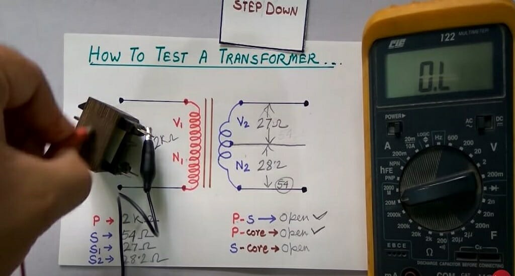
I’m getting open circuit readings for these two terminals. That means there are no issues between the core and the primary winding.
Step 5 – Test Secondary Terminals and Core
Now, test the secondary winding.
- Connect the multimeter’s black probe to one of the secondary terminals.
- Connect the multimeter’s red probe to the core of the transformer.
- Check the reading.
- Repeat the process for the other two terminals.
There are no issues here, too. I’m getting open circuit readings (infinite resistance).
Why is Checking the Transformer Without Power Important?
The above three tests (Steps 3, 4, and 5) cover all the components you need to check in a transformer. For instance, during Step 3, you are checking all the terminals. Steps 4 and 5 allow you to check the connection between the core and the terminals. Therefore, this is the ideal technique that you should use.
References
Website Resources:
- Open circuit – https://www.dummies.com/article/technology/electronics/general-electronics/closed-open-and-short-circuits-141399/
- Infinite resistance. https://www.sciencedirect.com/topics/engineering/infinite-resistance
Video References:
1929fordhotrod
Tech StudyCell