10 min read
How to Test a Transformer with a Multimeter (3-Step Guide)

Transformers are like the unsung heroes of our electrical systems, quietly working to transfer energy between circuits. But just like anything else, they can sometimes hit a snag and cause chaos in our circuits.
Knowing how to test your transformer is key to keeping everything running smoothly and safely. Here are the steps:
- Step 1: Review the transformer’s datasheet to understand the pin layout and connections.
- Step 2: Use your multimeter to measure resistance across specific pin sets, looking for a reading indicating a clear electricity path.
- Step 3: Verify that certain pin sets are not connected, using your multimeter to confirm no unintended connections exist.
Stay tuned, and I’ll take you through the process. Whether you’re a seasoned pro or just starting, you’ll find these steps easy to follow. Let’s make sure your devices stay operational and safe.
How to Test a Transformer with a Multimeter (Steps)
Let’s figure out if a transformer is in shipshape or waving a white flag. I’ll walk you through the steps, just like I learned, hands-on and straightforward.
Step 1: Know Your Transformer
First up, you have to understand what you’re dealing with. The data sheet for your transformer is like that blueprint. It’ll show you the layout of the pins and what connects to what.
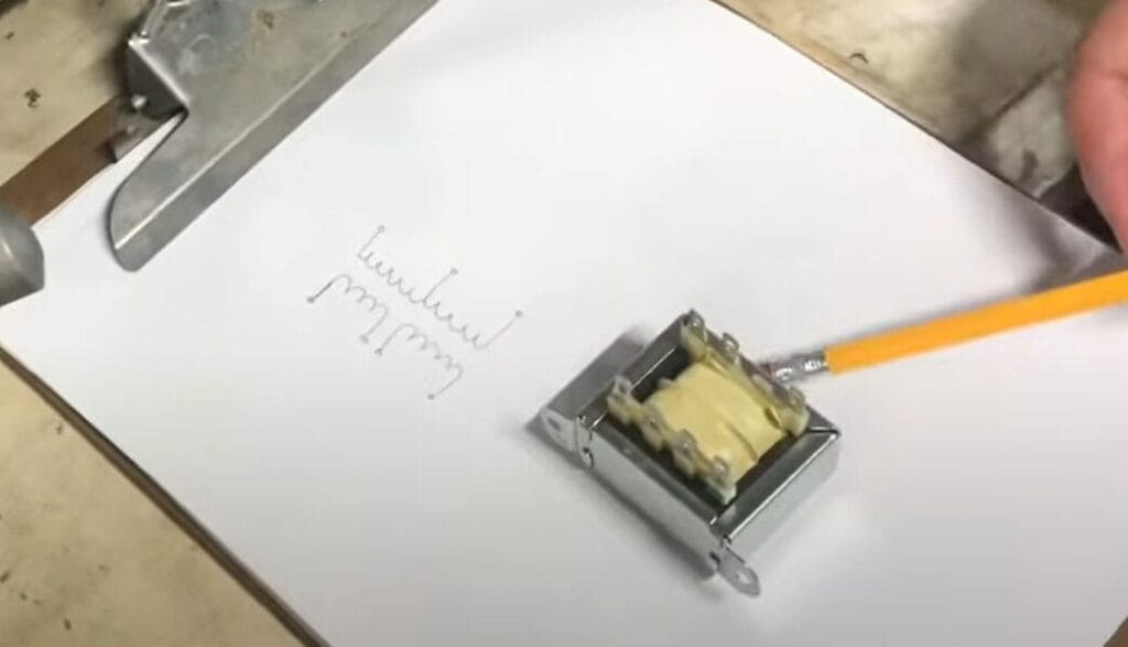
For example, if you’ve got four pins on one side that are supposed to correspond to another set, you’ll know where to start testing.
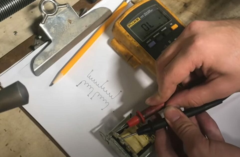
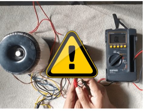
Step 2: Testing the Resistance
In a good transformer, coils act like resistors. So, grab your multimeter and set it to measure resistance. You’re going to check between specific sets of pins.
I got a few ohms between certain pins on one transformer I worked with, which was a good sign. Each set of connected pins should show some resistance, meaning the path is clear and electricity can flow.
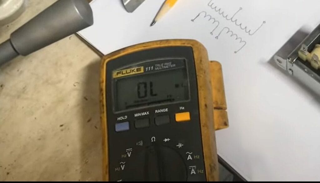
Step 3: Checking for Connections
On the flip side, you must ensure some pins are NOT connected. For instance, certain pin sets in some transformers should show no connection, and your multimeter should confirm that.
If it beeps or shows a reading where there shouldn’t be one, you’ve got a problem.
Remember, working with transformers is all about precision and patience. Take your time, follow the steps, and always double-check your work. Stay safe, and you’ll have that transformer figured out quickly.
Common Transformer Models and Their Testing Nuances
In the world of transformers, just like in any good workshop, one size doesn’t fit all. Different models have their quirks and features, and knowing these can make your testing much smoother.
Let’s break down a few common types and what to consider when testing them.
Step-Down Transformers
These are your typical household transformers, decreasing the voltage to a safer, more usable level. When testing these, I focus on the secondary winding – where the action happens.
Make sure your multimeter is set to check lower voltage levels here. It’s like adjusting your focus from framing a house to detailed interior work.
Step-Up Transformers

These bad boys do the opposite – crank up the voltage for long-range transmission. I’ve found that precision is key when testing step-up transformers.
You’re dealing with high voltage in the secondary coil, so make sure your multimeter can handle it, and don’t forget those safety gloves!
Isolation Transformers
Ah, the peacekeepers of the transformer world. They isolate circuits for safety and noise reduction. When I test these, I pay extra attention to the continuity between the primary and secondary windings. There should be no connection.
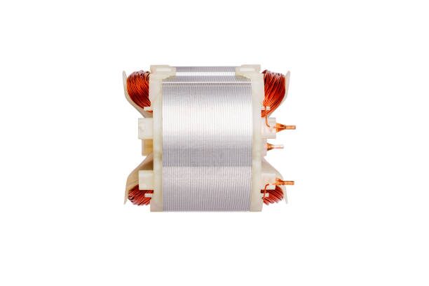
Toroidal Transformers
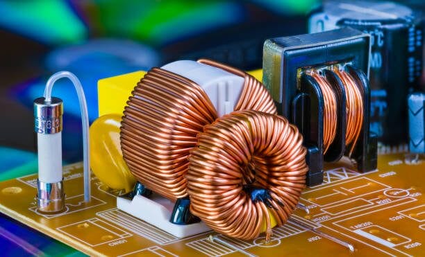
Their doughnut shape isn’t just for looks – it reduces electromagnetic interference.
Testing these can be a challenge because of their compact windings. I always take my time with these, ensuring I’m not just getting a surface reading.
Remember, understanding the specific model you’re working with is half the battle. With the right approach and patience, you’ll get an accurate reading every time. Stay safe, stay curious, and keep testing!
Safety Precautions
Let’s talk safety because it’s no joke when dealing with electricity. I’ve had my share of close calls, and trust me, you want to steer clear of those. So, here’s how you can stay safe while testing transformers:
- Power Down Before You Start: I can’t stress this enough. Before testing, ensure the device is completely disconnected from any power source.
- Choose Your Testing Spot Wisely: Find a dry and stable spot. Avoid areas where kids or pets can wander in. I remember once I had to set up barriers to keep a curious pup from an open circuit.
- Be Mindful of Exposed Circuits: When circuits are open, and you’re poking around with your multimeter, one wrong touch can lead to a shock or worse, damage the equipment. Use just the multimeter probes for contact.
- Respect Electricity: Electricity is powerful, and working with it demands respect and caution. Don’t consider plugging it in if you see a transformer with frayed wires or any visible damage.
- Know Your Stuff: This is key. Don’t dive into testing transformers unless you’re comfortable with electrical equipment. It would be best to have a solid grasp of using a multimeter for various measurements. If you’re new to this, spend some time getting familiar with the tool first. I learned a lot just by experimenting with different settings on my multimeter.
Remember, taking shortcuts is never worth the risk regarding electricity. Stay safe, be thorough, and always consult a pro.
Troubleshooting Common Issues
You will encounter a few roadblocks when tackling transformer testing with a multimeter. I’ve had my fair share of challenges in this arena, so let me walk you through some common problems and their fixes.
| Problem | Description | Solution |
|---|---|---|
| Inconsistent Multimeter Readings | Readings fluctuate or seem unreliable. | Ensure tight connections of multimeter probes. Check and replace multimeter batteries if necessary. |
| Zero Reading on the Multimeter | The multimeter shows zero or very low resistance, indicating a possible short circuit. | Check for short circuits in the transformer windings. The transformer may need replacing. |
| Infinite Resistance Readings | The multimeter displays ‘OL’ or infinite resistance, indicating an open circuit. | Inspect for broken wires or open circuits in the windings. The transformer likely needs replacing. |
| Overheating Issues | The transformer gets unusually hot during operation. | Check for overloading or insulation faults. Let the transformer cool before testing. |
| Buzzing or Humming Noises | The transformer emits noise during operation. | Tighten any loose laminations or mounting screws. Check if the noise persists after adjustments. |
| No Voltage Output | The transformer shows no output voltage. | Inspect for blown fuses or faults in the primary winding. Replace fuses if necessary. |
Testing transformers can be tricky, but you’ll get the hang of it with patience and attention to detail.
Common Mistakes and How to Avoid Them
When you’re testing transformers with a multimeter, it’s like walking through a minefield of potential mistakes. Trust me, I’ve stepped on a few of those mines myself. So, let’s talk about some common errors and how to sidestep them.
- Forgetting to Power Down: It might sound like a no-brainer, but you’d be surprised how often this gets overlooked. Always, and I mean always, power down and unplug the device before testing.
- Misinterpreting Multimeter Readings: This one can be tricky, especially if you’re new to using a multimeter. Misreading the measurements can lead you down the wrong path. I recommend double-checking your multimeter settings and understanding what each reading means. And if in doubt, check again.
- Testing the Wrong Connections: Crossing your wires is easier than you might think. This can lead to incorrect diagnostics. I always habitually double-check the transformer’s schematic before I start.
- Ignoring Safety Precautions: I can’t stress this enough. Safety is paramount. Working with electricity is not the time to cut corners. Ensure you’re in a dry, safe environment, use insulated tools, and wear protective gear. Remember, it’s better to be safe than sorry.
- Inadequate Preparation: Diving in without the right tools or understanding can lead to mistakes. Ensure you have a good-quality multimeter and are familiar with the transformer you’re testing.
- Overlooking Physical Inspection: Sometimes, the issue is right before you. A quick visual inspection can reveal problems like burns, bulges, or corrosion. I once missed a visibly fried component because I went straight for the multimeter. Sometimes, your eyes are the best tool you have.
By keeping these tips in mind, you’ll navigate the world of transformer testing much more smoothly. And always remember, everyone makes mistakes, but the smart ones learn from them. Stay sharp, stay safe, and keep testing.
Frequently Asked Questions
- Can A Transformer Be Repaired, Or Should It Be Replaced?
- Minor problems like loose connections can be fixed, but major issues like shorted windings or severe overheating often mean the transformer needs replacing.
- Can I Test A Transformer Without A Schematic?
- Testing without a schematic is tricky but not impossible. Start with a visual inspection and identify the primary and secondary sides based on wire thickness and color. However, having a schematic is always the best practice.
- How Important Is The Polarity When Testing A Transformer?
- Getting the polarity right is crucial, especially when testing the primary and secondary windings for phase relationships. Incorrect polarity can lead to misleading test results.
- My Transformer Passed The Continuity Test. Is that okay?
- Passing a continuity test is a good sign, but it doesn’t rule out all issues. Perform voltage and load tests to assess the transformer’s health. It’s like passing a vision test; you still need a full physical to be sure everything’s okay.
References
Organizations:
- Institute of Electrical and Electronics Engineers (IEEE). https://www.ieee.org/
- The International Electrotechnical Commission (IEC). https://www.iec.ch/homepage
Books:
- “Transformer Engineering: Design and Practice” by S.V. Kulkarni and S.A. Khaparde. https://www.abebooks.com/9780824756536/Transformer-Engineering-Design-Practice-Power-0824756533/plp
- “Handbook of Transformer Design and Applications” by William M. Flanagan. https://www.barnesandnoble.com/w/handbook-of-transformer-design-and-applications-william-m-flanagan/1101089686
Website Resources:
- All About Circuits. https://www.allaboutcircuits.com/
- Electrical4U. https://www.electrical4u.com/
- EE Power. https://eepower.com/
Video References:
Live Free