7 min read
How to Connect Thermocouple Wire (Steps and Breakdown)
Navigating the intricacies of connecting thermocouple wires begins with understanding their wiring.
Typically, the wire designed for negative terminals is either red or white, while the one for positive terminals varies based on the thermocouple type. For example, the yellow wire connects to the positive terminals with a Type K thermocouple. Ensure you use the correct wire type to match the specific thermocouple, as each has its unique metallic combination.
This article provides a detailed guide on various thermocouple types and dives into their functionalities, applications, and calibration.
Connecting a Thermocouple Wire
We shall focus initially on connecting the wires to a Type K thermocouple because it has a wide temperature range (-328°F to 1652°F) and is the most durable and popular.
However, some principles apply generally to all thermocouples (see further below under principles).
Wiring a Type K Thermocouple
You will need a K-type thermocouple wire to wire a Type K thermocouple.
In a Type K thermocouple, the positive wire is yellow, and the negative one is red.
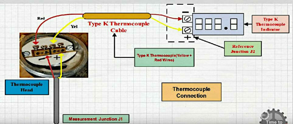
Connect the wires from each end of the thermocouple as follows:
- Connect the yellow wire to the positive terminals of the thermocouple head and the reference junction (or thermometer).
- Connect the red wire to the negative terminals of the thermocouple head and the reference junction.
Wiring Other Thermocouple Types
Other thermocouple types are wired similarly, but the colors, which help distinguish the thermocouple type, may differ.
Refer to the table and chart below to know which wire to connect to the positive terminals at both ends and which one to the negative terminals. These color codes only apply to the ANSI/ASTM E230 standards (not IEC 60584).
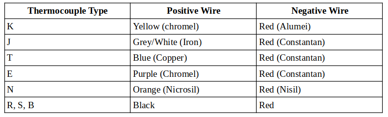
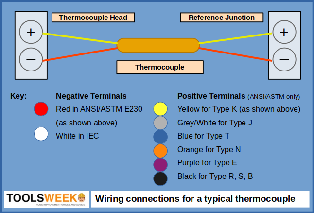
(ANSI/ASTM standard)
A Practical Demonstration (for Type K)
Here, I will give an example of wiring a high-temperature K-type thermocouple, which is typically used for a kiln, furnace, or forge.
One end of the thermocouple wire (Type K only) is attached to the thermocouple’s head, and the other will connect to a digital thermometer as the measuring instrument (reference junction).
Step 1: Connect the Thermocouple Head
Connect the thermocouple to its head, as shown below.
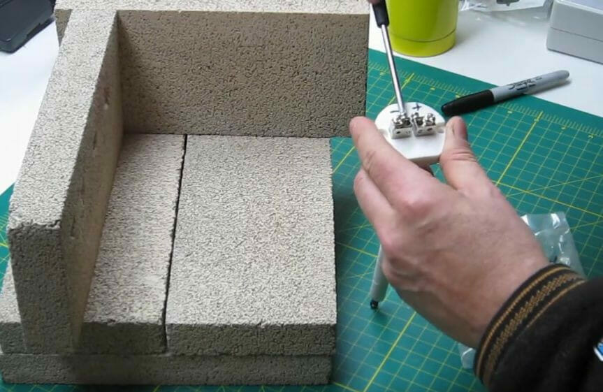
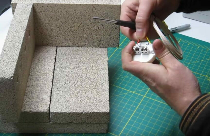
Step 2: Connect the Wires to the Head
Connect the thermocouple’s wires to the right terminals on the thermocouple’s head, as shown below.
Remember, red is usually always connected to the negative terminal and the other colored wire to the positive terminal, as explained earlier.
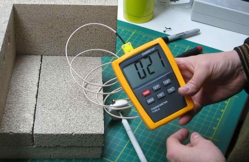
Step 3: Connect to the Digital Thermometer
Connect the other end to the digital thermometer, observing the correct polarity (red to the negative terminal).
Thermocouples
Function and Operation
A thermocouple is a type of sensor that measures temperature.
It converts the heat energy from two different types of metals joined together at one end into electrical signals. The voltage is interpreted when it is heated (or cooled) to allow the current to flow, stop flowing, or provide a temperature reading.
Generally, the non-zero voltage measured by a thermocouple is about 10µV for a temperature difference of 1°C (Christine Lefrou et al., 2009).
Constantan, which is commonly used for the negative wire, is an alloy of nickel (45%) and copper (55%). The positive one is made from various metals (see the table above).
Uses
Thermocouples are used in a wide range of ways wherever a process depends on a certain temperature.
Types
Thermocouples come in a variety of types. The most common are:
- Thermocouple wire
- Thermocouple probes
- Thermocouple probes with connectors
- Transition joint thermocouple probes
- Bare wire thermocouples
- Infrared thermocouples
Calibrations
Different metal combinations in thermocouples have different calibrations. The most common thermocouple calibrations are:
- General-purpose thermocouples: Type K (cheapest)
- Base metal thermocouples: Types J, K, T, E, and N
- High temperature (Noble Metal) thermocouples: Types R, S, C, and GB.
Different calibrations operate with different temperature ranges, but the diameter of the thermocouple wire also limits this range. Generally, the thicker the thermocouple wire, the wider the temperature range it can work with.
Usually, the temperature range of a thermocouple determines which type you should use. Other important factors when choosing one include vibration, abrasion, and chemical resistance; required accuracy and response time; and the installation requirements.
Principles of Connecting Thermocouple Wire
The general principles when connecting thermocouple wire are to maintain the correct polarity, use only the same type of thermocouple, and use only thermocouple wire. I’ve also added two more relating to wiring into a switch or junction box and keeping away from power wiring.
Maintain Correct Polarity
Thermocouple wires are positive or negative. Observe the correct polarity when wiring one.
Thermocouples are usually wired as follows: The negative wire is red in ANSI/ASTM-compliant thermocouples and white in IEC color-coded ones.
The thermocouple’s measurements will be in error if you reverse the polarity.
Use the Same Type of Wire
It is important to match and use the same type of wire as required by the thermocouple to maintain accuracy (refer to the table above).
The different colored thermocouple wires are for different types of thermocouples. You shouldn’t mix the types and wires.
Use Only Thermocouple Wire
Use only thermocouple wire for extending the wiring. It may be described as a “thermocouple” or a “thermocouple grade” wire.
Don’t use ordinary copper wire. A non-thermocouple wire is susceptible to giving a wrong reading.
If the wiring run is long, I suggest you use thermocouple wire for the initial portion, to connect to the thermocouple head, and “extension” or “extension grade” wire for the rest, as it will be cheaper and will work fine.
Switch or Junction Box
When wiring the thermocouple into a switch or junction box, the contacts don’t need to be the same as the thermocouple materials.
Keep Away from Power Wiring
Don’t run thermocouple wires inside conduits that carry power wiring. Also, don’t run them alongside any heavy power-carrying conduit or electrical bus bars. You can cross them, though, if you need to.
If the possibility of interference is high, I suggest you use wire shielding around the thermocouple wire.
References
Christine Lefrou, Pierre Fabry, and Jean-Claude Poignet. Electrochemistry – The basics with examples. Springer. 2009
K-type thermocouple wire and high-temperature sensor. https://www.meter-depot.com/k-type-thermocouple-wire-high-temperature-sensor-pk-1/
Video References:
Calibration Academy
Carsten Franke