14 min read
How to Wire Recessed Lighting Diagram (Guide with Photos)
Recessed lighting fixtures are an excellent addition to any area, providing subdued, indirect lighting with a warm, inviting atmosphere. They provide a sleek, pleasant alternative to more visible fixtures, from a string of pot lights around your house to mood lighting in your den. But what if you find yourself in a situation where you need to wire your recessed lighting and you don’t know where to start.
A great place to start is with a wiring diagram and below we will cover this as well as how to wire your recessed lighting in detail.
In general, you can wire and install your recessed lighting in your ceiling in five easy steps:
- Pick and cut your desired lighting spots in the ceiling
- Turn off the power supply and identify the power source
- Run and connect your recessed wiring through the ceiling and junction boxes
- Properly wire your recessed lighting
- Install your recessed lighting’s trim and lamps
In this article, let me walk you through more details on how to properly wire your recessed lighting, the things you’ll need, and the essential tips to consider when purchasing and installing recessed lights.
9 Steps to Wire Recessed Lighting With Diagrams
Things You’ll Need
When you are wiring or adding recessed lights, you’ll need the following:
- Drill with drill bits
- Stud finder
- Measuring tape
- 4-in-1 screwdriver
- Electrical tape
- Fish tape reel
- Drywall saw
- Non-contact voltage tester
- Wire cutters and strippers
- Wire caps
- Switch box
- Junction boxes
- Light switch
- Needle-nose pliers
- Stepladder
- Appropriate electrical wire
- Recessed light fixtures
Step 1: Plan Your Lighting Layout
Planning is the key to getting your recessed lights in the right spot. With that, you should plan the following:
Locations
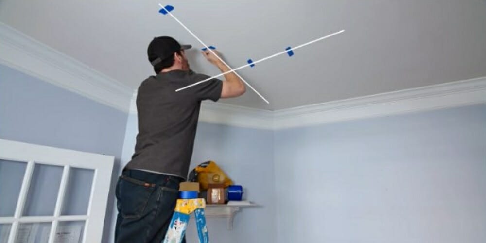
Whatever your goal is for installing or adding recessed lights on your ceiling, the first step is to figure out which areas will be illuminated by that circuit. Also, how many accent light fixtures will be necessary, along with their optimal positions, to ensure sufficient illumination coverage. Using painter’s tape to temporarily mark each fixture’s location will allow you to move some of them about while picking the suitable locations without leaving any extra marks on the ceiling.
Fixtures
Shop around for your desired fixtures. Also, knowing the rating and the number of fixtures you plan to install will allow you to determine the combined maximum power of all the fixtures so that a properly sized breaker and wiring can be determined. For example, since LED lights consume much less power than halogen and incandescent lights, you can downsize from a 20 amps circuit to a 15 amps circuit.
Switches
The next step is to determine where the switching will come from. Would you use an existing switch, or will you need to install a new one? How much cable will you need to reach the electric panel, and how much extra to get the closest light fixture on the new circuit? You should answer all those questions.
Cable Layout
If you carefully organize your work ahead of time, you can save a little money on this project’s final cost by avoiding ill-conceived runs. So, find out the most efficient approach to link all of the fixtures to a power supply or an activation switch. You can use either.
A. The 120V source from the switch
If the shortest distance connects the switch cable to the fixture at one end of the circuit, you will insert the switch cable into its electrical box.
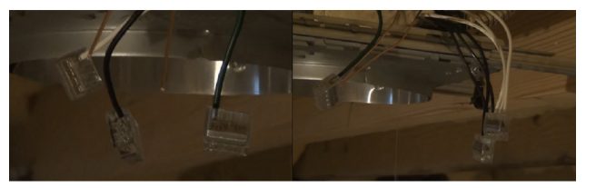
Then, it will be connected to the fixture and the line leading (or feeding) the next fixture in the circuit. Make sure all white wires are connected, all black wires are connected, and the Gnd and green wires are pigtailed together and connected to the ground in the junction box.
If the cable from the switch needs to be fed to one of the intermediate fixture’s junction boxes due to its proximity, the wiring is still done the same way described above. However, it will make it a little more crowded. It’s because there are already two cables inserted, one from one end of the circuit and the other from the other.
Then, along with the third set of wires from the fixture itself, the switch’s cable provides the 4th set of wires inside that box.
B. The live cable is fed directly from the electrical panel
In this scenario, where the shortest distance or another complication results in feeding the cable from the electric panel to one of the fixtures instead of the switch, the wiring connections will be slightly more complicated and hazardous. But it’s still possible, as long as the power and switch cables are routed to the same junction box. It will add another set of wires to that junction box.
For the connection, the panel’s black wire and the switch’s white wire will be singled out and pigtailed together.
Then, ensure that there’s black electrical tape wrapped around the switch’s white wire to indicate that it is, in effect, another Live line and not a Neutral.
With this knowledge, you can calculate the length of wire required to connect the switch box to the proper fixture.
You’ll also need to measure and add the lengths between each succeeding light fixture in each branch.
Finally, for every cable connecting two junction boxes, add two feet (600 mm) minimum to provide around 8-10 inches (200-250 mm) of slack at each box to make the connections of each fixture and switch in that circuit.
Cable and Breaker
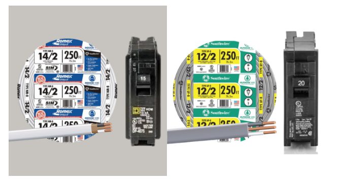
If you utilize a 14-gauge wire to power your circuit, you’ll need a breaker with a maximum rating of 15 amps, which is the circuit’s full load (measured in Watts).
The total wattage of all the fixtures in your circuit determines how many fixtures a 14-gauge cable can carry.
To get the maximum feasible circuit watts, use the following formula:
Watts = Volts x Amps
A 120-volt circuit with 14-2 cables can only carry 1800 Watts (15 rated amps). If you want to add lighting that consumes more than 15 amps, you’ll need 12/2 cables and a 20-amp circuit breaker. Then, you may now shop for fixtures and the proper size wires and breakers using the information you’ve obtained.
Caution: If you want to add one or more outlets to that circuit, you need to upgrade the wiring to 20 amps because you never know what kind of device will be plugged in at any given time.
Step 2: Check for Joists

With a stud-finder, check around each position for joists and trace out the optimum location for the fixtures so you don’t cut on the framing grid, which would prevent the electrical box from being installed. The recessed light kits usually include a template, which you could use to trace the opening’s cutout where the painter’s tape is.
Step 3: Pick and Cut Your Desired Spots
With a stud-finder, check around each position for joists and trace out the optimum location for the fixtures so you don’t cut on the framing grid, which would prevent the electrical box from being installed.
The recessed light kits usually include a template, which you could use to trace the opening’s cutout where the painter’s tape is.
After picking spots, cut a 12- to 16-inches wide piece of drywall from the ceiling if you don’t have access to the joist gaps from the attic. That way, you can access the ceiling joists and the top of the wall.
Cut the slot about 6 inches perpendicular to the joists. Make it long enough to reach all the joist spaces where you will install a recessed fixture and a power supply. The aperture should ideally be aligned with the switch and power source, allowing you to drill through the top plate. If not, you may need to make a new cut.
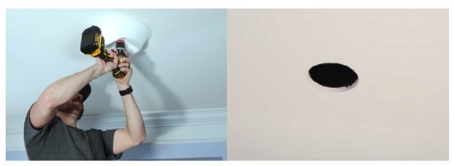
Then, cut out the holes for the recessed lighting. To ensure that your recessed light housings will fit, drill a tiny hole and measure the depth of the joists before cutting any holes. Most lighting requires approximately 7 inches. E
Examine each joist space for obstacles using a flashlight through the slot. Then, following your plan, measure and mark the center of each recessed light, adjusting as necessary to avoid joists and other impediments.
Finally, measure and cut housing holes.
After that, create a cable route for carrying wires through wall plates and sills, joists, and wall studs by drilling through the top plate and joists. Maintain a 2 inches gap between the holes on the plate between the joists’ top and bottom.
You can use a rotary tool with a specific bit, a keyhole saw, or a utility knife for the cutting process.
Step 4: Turn Off the Power Supply
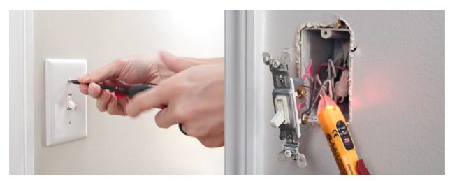
Before proceeding with the installation, switch off the breaker that controls the ceiling light’s electrical circuit. With a screwdriver, remove the switch plate from the light switch and place a non-contact electrical tester against the wires on the switch’s side. The circuit is still powered if the tester’s light comes on. Turn down more breakers, or the house’s main circuit breaker, then test again to check that the circuit is completely shut down.
Step 5: Identify the Power Source
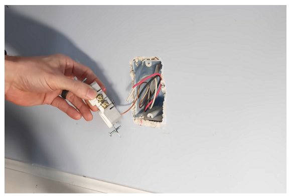
Find an existing box to utilize as a power source. Break it open and fish a power line to the new switch location through the hole. Find a current switch box or receptacle with a hot wire and on a suitable circuit to power your recessed lights.
Any connections to “dedicated” circuits, such as 20-amp small-appliance circuits in kitchens or dining rooms, 20-amp laundry room circuits, and 20-amp bathroom circuits, are prohibited by the National Electrical Code.
Step 6: Run Your Wirings
Drop your weighted fish tape string through the opening in the top plate. Since the old box is already out of position, use its opening for fishing in the new cable.
Tape the cable’s end to that opening after running your weighted string to that opening. Then with your fish tape reel, pull the cable up and through the hole in the switch, then back through the joist spaces to get them through tricky and tough sections.
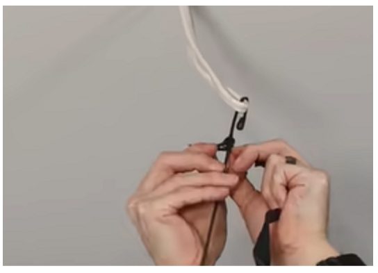
Allow around a foot (300 mm) of your cable that will be hanging out for lighting connections later on. Moreover, remove approximately 6 inches (150mm) of the jacket from each cable end coming out of each fixture aperture, exposing the color-coded wires, then remove approximately 1/2 inch (12mm) of insulation from each insulated wire.
Step 7: Fix the Junction Boxes
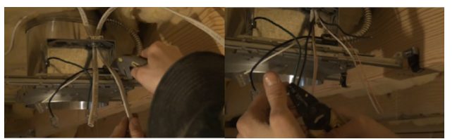
In your open ceilings, fix typical “new work” housings. Connect cables connecting to other low-voltage fixtures using the junction box on this fixture. Afterward, run around 8 inches (200 mm) of wire through each cable clamp and place the cable connections in their corresponding junction boxes. Then, remove a knock-out plug from the same side of each junction box for each cable coming out of each opening. It is to give a slimline assembly for easy insertion through the openings.
Note: You’ll save money if you buy fixtures with a built-in junction box. However, they only provide a small amount of room for connections, which may require an additional junction box installation.
Step 8: Install the Remodeling Housings and Remodeling Box
Before you install the housings in the ceiling, wire them up. Follow the manufacturer’s instructions when wiring and mounting your fixture. Then on the remodeling box, label the power and switch cables before putting them in your remodeling box. The box should then be slid into your old outlet location and secured with screws. After that, connect your new wires to its power source, and reconnect the new outlet. (1)
Step 9: Install Your Recessed Lighting’s Trim and Lamps
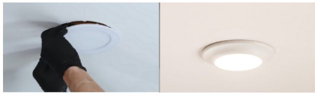
Fastening clips are commonly included with recessed lighting installations. To properly adjust the clips, refer to the instructions as they are different between models.
Then, according to your plan, install the trimmings and bulbs, ensuring everything is secure and safe. Then, replace the ceiling drywall and seal the ceiling. Finally, add finishing touches like painting your ceiling to make it look neat and new.
Essential Installation Tips
- Before fishing a cable length through the framing, uncoil, cut off, and straighten a size at least 15% longer than you believe you’ll need.
- At each aperture, you should leave around 2 feet of excess cable.
- Staple the cable to the joists in the areas where you have access to them.
- You should run only one or two cables through each 3/4-inches hole you’ve created. Maintain the holes at least 2 inches between the joists’ top and bottom.
- Strip 12 inches of sheathing before putting the cord into the electrical box. The sheathing should be 1/4 inch thick beyond the clamp.
Purchasing Recessed Lights
The housing, trim, and lamp make up a recessed light assembly. The appropriate trim styles and lamps are listed on labels within the enclosure. Failure to follow the standards might cause ineffective illumination and, more importantly, dangerous overheating.
Lighting showrooms typically provide a larger selection and salespeople to assist you with lighting design and order. Catalogs from manufacturers are another excellent source of knowledge, as they contain a comprehensive list of housings, trim styles, and lamps, as well as design recommendations and technical information. (2)
Furthermore, standard housings with mounting brackets are best for open frames. If you plan to add recessed lights coated with insulation, make sure to get IC (insulation contact) housings. Non-IC housings will require a minimum of 1/2 inches for combustible separation and a minimum of 3 inches for thermal insulation separation. In insulated ceilings, look for airtight housings for added energy efficiency.
Take a look at some of our related articles below.
- How to run wire through walls horizontally
- How to wire lights on a 48 volt golf cart
- How to wire lights in parallel with switch diagram
References
(1) power source – https://www.sciencedirect.com/topics/engineering/
power-source
(2) excellent source of knowledge – https://link.springer.com/article/
10.1007/s11229-018-02056-x
Video References
Fix This Build That
D.I.Y. Remodel Videos