8 min read
How is a Three-Way Switch Wired?

Wiring a 3-way switch is not as complicated as you might think. I’ll show you how it’s done.
Quick Summary: To wire a 3-way switch per the in-line arrangement, connect the hot wire from the power source to the primary switch’s common terminal, the second switch’s common terminal to the load, and the two corresponding traveler terminals on each switch to each other.
I’ve explained the wiring procedure with illustrations and an alternative configuration for the same effect below.
3-Way Switches
3-way switches are always used in pairs.
A 3-way switch does not have any on or off position marked on it because this varies depending on the state of the other 3-way switch.
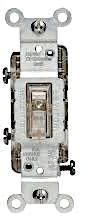
Internally, it has three terminals, all in brass (for hot wires only), because a neutral (white) wire is NEVER connected to it. On one end of the switch (or the center) will be a terminal marked “common” or COM, and the other two unmarked ones are called “travelers.”
In this 3-way switch (below), the two terminals on one side are the travelers, and the single terminal on the other is the common one. But your one might differ, so check the markings.
First, let’s recap an important precaution and then see why it’s necessary.

As with any other switch, use a 3-way one only for the hot/live wire. It won’t work if connected to the neutral wire. The extra terminals in a 3-way switch are ONLY for hot/live wires, NOT for the neutral or ground wires. Connecting hot and neutral wires in the same switch will create a short circuit and burn the wiring. Only connect the neutral wire to the power source and the load.
Why a 3-Way Switch is Necessary
A light switch in a room is normally attached near its entrance.
But if you have a large room, hall, staircase, garage, or multiple entrances to an average-sized room, you must wire a 3-way switch. It’s the only solution for convenient control of the lighting circuit and to avoid having to pass through the room in darkness.
You cannot use an ordinary single-pole, single-throw switch, AND, OR gate. The solution is to wire a 3-way switch circuit. It will allow you to control the load from either of the two locations.
The load is usually a light fixture, but it can be anything you want to control with a switch from two places.
Type of 3-Way Switch Wiring Arrangement
To wire a 3-way switch correctly, decide whether an in-line or switch-loop configuration is appropriate. [Herres, 2015]
The choice depends on whether it’s more convenient to initially provide power to the first or primary 3-way switch (also called the hot end), the second one (or leg end), or the load. The in-line configuration is suitable for most general cases. Both switches are located (electrically) in this configuration between the power source and load.
The switch-loop configuration is an alternative wiring arrangement to the in-line configuration with the same effect. It is ideal when running power directly to the load and then to the switches from there is better.
Other arrangements are possible, but they are dangerous and illegal.
Wiring a 3-Way Switch
If the switch boxes are not already attached, attach them to the desired locations, usually near two entrances or endpoints, so they can be easily switched by hand upon entering.
If you don’t do electrical work regularly, remember the basic rule that a switch is only added in a circuit’s hot (aka live) branch. It is never connected to the neutral wire, nor is a neutral wire connected to a 3-way switch.
Wire
Use 12-2 AWG Romex wire for wiring a 3-way circuit switch, which should be sufficient for a lighting circuit. You can use thinner 14-3 wire for the portion between the two traveler terminals, but using the same 12-2 wire throughout is better.
Procedure for In-Line Configuration
Here’s the procedure. It doesn’t matter which order you do them in:
- Run the black wire from the power source to the common terminal of the first 3-way switch.
- Connect the two traveler terminals of the first and second switches, as shown in the diagram below. You can use one red and one black wire to distinguish them, which denotes the hot wire. It doesn’t matter which one is connected to which terminal except that the terminals are corresponding ones to keep it simple.
- Run the black wire from the common terminal of the second 3-way switch, i.e., the one farther away from the power source, to the load.
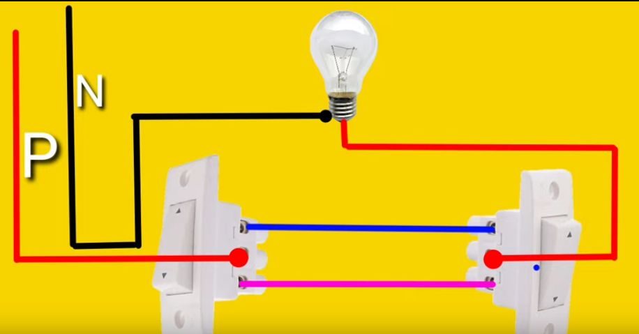
Below is a wiring illustration for a lighting circuit taken from a non-US wiring source.
The red, blue, and pink wires are all hot or live wires. They are connected ultimately to the source terminal marked P, which stands for “phase.” In the United States, you normally use black wires for these circuit parts. But, as I said, you can use red wire for one of the two traveler-to-traveler terminals between the switches.
The wire shown in black here, connected to the N (neutral) source terminal, is the white wire.
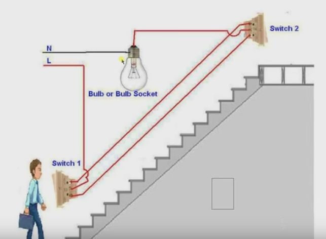
Below is a wiring illustration for a staircase.
The wiring arrangement is the same as above. The red wires connected to the L terminal of the supply are the hot or “live” wires, which are either black or red in the United States. The black neutral wire shown here is white in the United States.
Procedure for Switch-Loop Configuration
Follow this arrangement for a switch-loop configuration, where the power is connected directly to the load:
- Instead of connecting the ungrounded conductor to the load, wire-nut it through the nearer 3-way switch and then to the farther one’s common terminal to function as the input.
- Connect the neutral (white) wire from the power source directly to the load’s neutral terminal.
- Run a wire from the first 3-way switch to the load and another between the two 3-way switches. Again, you can use different colored wires to connect the travelers to distinguish them.
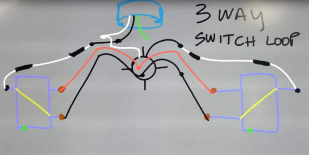
In the illustration below, the electrician used white wire to connect the load to each switch’s common terminal but re-identified them as black using black electrical tape.
Checking and Extending
Continuity Check
The pair of 3-way switches will function as a normal single-pole, single-throw switch because the continuity is between the two common terminals when powered.
When checking a 3-way switch, set the multimeter to the ohms function.
You will see that there is never continuity between the traveler terminals, only between the common and either of the two traveler terminals in only one position (and not in the other). This is as it should be because each switch position connects to only one of the two traveler terminals, never to both simultaneously.
Extending the Circuit (More than Two Switches)
A 3-way switch comprises two switches only. If you need more than two, use four-way switches instead along the traveler lines. We have a separate article for that.
References
3-way switch. https://www.homedepot.ca/product/leviton-3-way-lighted-toggle-switch/1000167435
Video References
Electric Fitting Videos
Electrician U
Niket Shah Plus