9 min read
How to Wire a Blower Motor to a Plug (5 Steps)
You’ve come to the right place if you’re looking to wire a blower motor to a plug.
Attaching a power cord is essential to power the blower motor, but you must also attach other parts, including the capacitor, to make it operational. So, I will cover the wiring procedure thoroughly to help you get your blower motor up and running.
To wire a blower motor to a plug, attach one of the speed wires, i.e., red, blue, or black (from low to high) to the power cord’s black wire, the two neutrals (white wires) together, and the two ground wires (yellow or green) together. However, you must also connect the two brown wires from the motor to a capacitor to make it operational. Also, attach the control board for greater control over the blower motor’s speed.
First, learn the different attachments and wires connecting to the blower motor.
Get to Know the Attachments, Wires, and Specifications
External Attachments
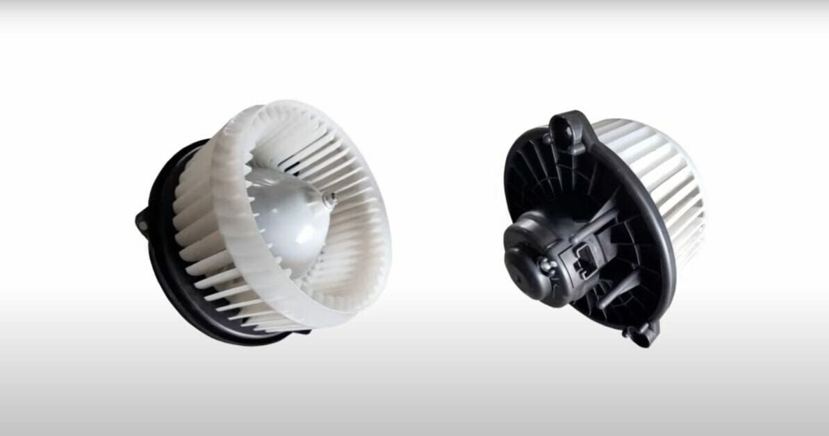
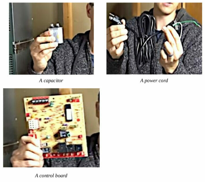
A blower motor connects externally to three main electrical items: a capacitor, a power cord, and a control board. Our focus is connecting with a power cord (see the second picture below).
Direct Attachments
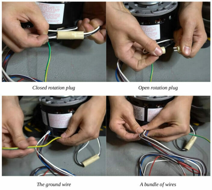
Additionally, the blower motor has a rotation plug, a ground wire, and an additional bundle of wires:
- The rotation plug is attached directly to it. Its function is to set the motor’s direction of rotation.
- Like the one below, the ground wire is usually yellow, green, or striped in both.
- The bundle of wires is provided according to whether it is a 2-, 3-, or 4-speed motor. The one shown here is a 3-speed motor.
Wires
Here’s a list of the wires you would typically see on a 3-speed blower motor:
| Wire (Color) | Function or Connection |
| Brown with white stripe (or brown only) | Connects to the capacitor |
| Brown | Connects to the capacitor |
| White (or yellow or purple) | Common or neutral |
| Red | Low speed |
| Blue | Medium speed (for normal air) |
| Black | High speed (for dense air) |
| Yellow (or green or green/yellow striped) | Ground |
A 4-speed motor has an extra wire for the speed function, so you will have 4-speed wires instead of the 3 listed above.
Specifications
The label on the blower motor specifies its electrical features. Below is a sample of one blower motor label, which also has external electrical connection diagrams on it.
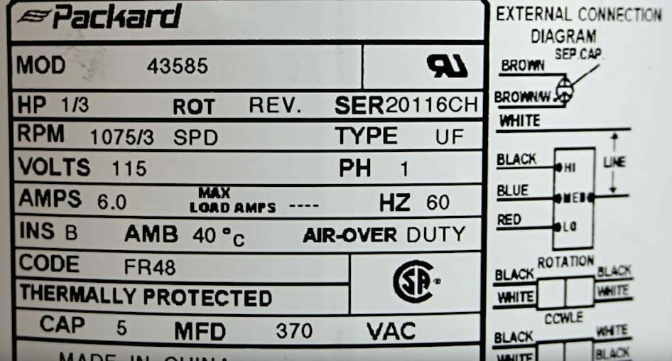
Let’s take a look at the electrical connection diagrams:
The top diagram is for the capacitor to which you connect the brown wires.
The second one shows the 3-speed wires (red, blue, and black) and 1 (white) common wire. The different speeds maintained by the wires have different resistances.
The bottom shows the wires inside the attached rotation plug, which are black and white. One part shows that attaching the corresponding wires is for normal counter-clockwise rotation, whereas reversing them will change the rotation to clockwise.
Wiring the Blower Motor to a Plug
Let’s begin by wiring the blower motor to a power cord with a plug.
Step 1: Identify the Wires
Notice that the power cord has three black, white, and green wires.
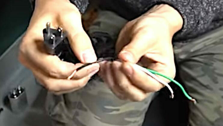
The 3 wires serve the following functions:
| Wire (Color) | Function or Connection |
| Black | Hot or line voltage |
| White | Neutral |
| Green | Ground |
However, to make the blower motor functional, you must wire it to a capacitor and connect the other provided wires. So, we will have to cover these attachments as well. Then, I will show where to connect the above 3 power cord wires.
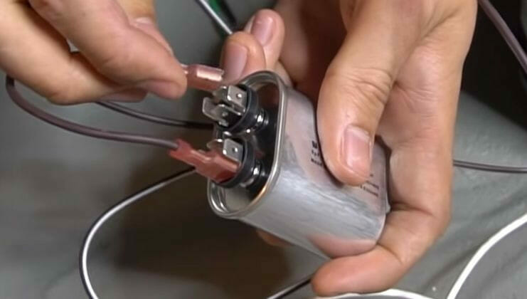
Step 2: Attach the Capacitor
In this case, the capacitor is a 5 µF castor oil-protected capacitor, although yours may differ depending on your blower motor.
It has two terminals, and each terminal has 4-prongs. It doesn’t matter which of the two brown wires goes where. You can attach one each to either terminal and any of the four prongs as is convenient.
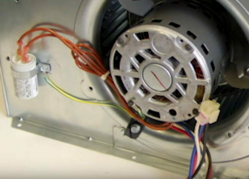
The furnace normally has a bracket to hold the capacitor, as shown below. If the bracket is missing, you can use a steel hanging strap or zip tie to mount it in a convenient place but don’t leave the capacitor hanging or dangling on the floor. Mount it somewhere.
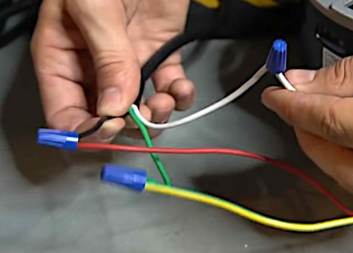
Step 3: Wire the Speed and Common Wires
Wire the speed and common wires as follows (to the wires from the power cord):
- Combine the red wire from the motor and the black wire from the power cord and attach a wire cap over the joint.
- Combine the two white (neutral) wires together.
- Combine the two ground (yellow or green) wires together.
Note that we only connected ONE of the 3-speed wires directly to the black wire on the power cord. Later, I will show how to connect the control board to all 3-speed wires to make all 3 different speeds available.
Step 4: Test the Blower Motor
After attaching the capacitor to the blower motor and wiring it to the power cord with a plug, you are ready to plug in and test it.
Use a multimeter with a clamp to test the blower motor wiring.
The current draw through the red wire in the example below is 1.25-1.28 A.
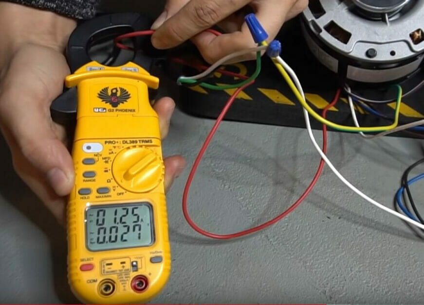
Note that this amperage reading was for the low-speed (red) wire. If you attach a higher-speed wire (blue or black) instead, you should get a higher amperage reading. Also, with the attachment on the blower motor’s shaft, you should get even higher current readings (and louder spinning sounds) due to the extra load it tries to handle.
Step 5: Wire the Control Board (Optional)
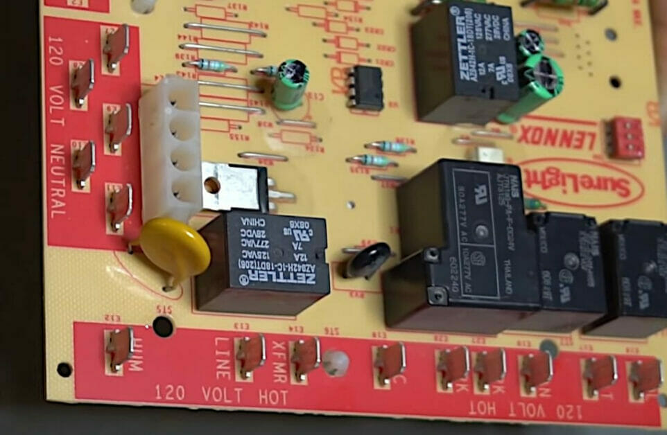
You will notice two zones with pins on the control board: ‘120 Volt Neutral’ and ‘120 Volt Hot’.
Although each has several pins, they are all connected to the neutral bus. So you can use either one of them for each blower motor. But the hot zone has pins for different appliances or speeds.
In the example below, the hot zone is along the bottom, and the neutral (or common) one is on the left.
Take a closer look at the hot zone:
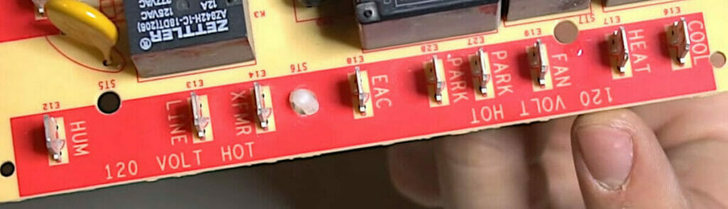
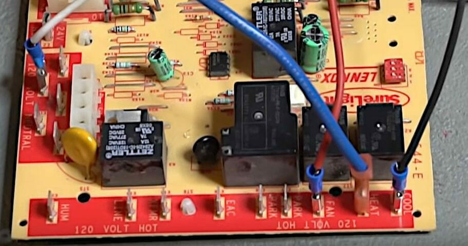
A blower motor is ideally connected to the hot pin on the control board marked ‘cool’, ‘heat’, and ‘fan’. I suggest connecting the black, blue, and red wires to them, respectively, and the white ones to any of the pins in the neutral zone.
If you don’t want to use a particular motor speed, i.e., you want to disable one of the speed wires, connect it to the ‘park’ pin.
References
Video References:
EasyAutoFix
Word of Advice TV