8 min read
How to Wire a Thermostat to a Modine Heater (8 Easy Steps)
If you want to wire a thermostat to a Modine heater, I’ll show you how to do it Below!
There are many models of Modine heaters and numerous thermostats in the market. So, you must match the heater and thermostat by considering their operating voltages, wattages, and wires. Then, wire as follows:
To wire a thermostat to a Modine heater, you only need to attach wires to the R and W terminals. In a typical, simple setup, you attach the black wire to the W1 terminal on the thermostat and the white wire to the R terminal. Attach the black wire to the T1 terminal on the Modine heater and the white wire to the T2 terminal.
Although this might work for you, if it doesn’t, I’ve given details of a few variant models and links to obtain the specific wiring instructions for your particular Modine heater and thermostat.
Modine Heaters
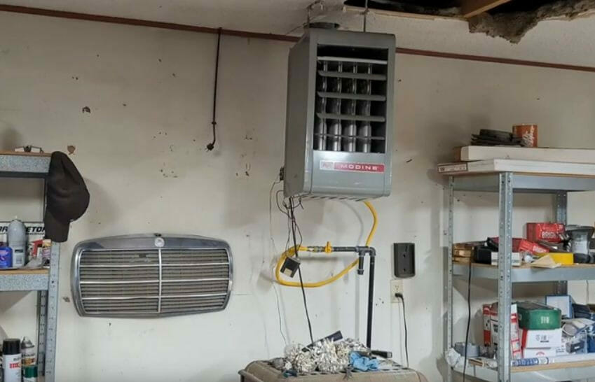
Modine heaters come in two general types: oil-fired ones, usually with black iron pipes and fittings, and gas-fired ones, usually with copper tubing and fittings.
The wiring scheme differs between the different types. The wiring in oil-fired Modine heaters is usually the same as for electric furnaces, whereas gas-fired Modine heaters usually require separating wiring for the thermostat. The number of wires required may also differ.
Heating systems also fall into two general categories, and knowing which one you have is important to do the wiring accordingly: forced air (hot air) and hydronic (hot water).
Before Wiring
Make sure you know what type of Modine heater you have.
Also, ensure its power is turned off before you start wiring it.
Generally, regardless of the type of heater, you can pair the heater and thermostat as long as the voltages, wattages, and wires match.
If installing the heater, it is usually placed near a baseboard or ceiling, on a wall. Please don’t install it with acid, chlorinated, or halogenated vapors in any area. A thermostat is normally attached in a central location in the house, away from a window or vent, to minimize potential interference. Still, you may install it close to your Modine heater if it will control it solely.
Requirements
You will require some or all of the following items when wiring a thermostat to a Modine heater:
- Tools: wire cutter, wire stripper, screwdriver, adjustable wrench
- Materials: electrical tape
The manufacturer may supply the wire; otherwise, heaters and thermostats typically use 10- or 12-gauge wire.
Precautions
Observe the following precautions issued by Modine:
- Disconnect the power supply before making wiring connections to prevent electrical shock and equipment damage.
- The wiring must conform with your local building codes or the NEC ANSI/NFPA 70.
- Protect the heater’s power supply with a fused disconnect switch.
- Only provide the heater with the voltage stated on its serial plate.
- Modine heaters with 25V controls require a step-down transformer with a VA rating exceeding the connected electrical load.
- Don’t electrically energize the heater until it has a gas connection, which could cause control components to fail.
- Don’t locate any wiring directly above or below the heater, as it could overheat the wires. They must not touch the heater’s sides, either.
- Give adequate ampacity and insulation temperature to the control wire used to connect the heater to the thermostat.
- Replacing the original factory wiring must have a temperature rating of at least 105°C.
Wiring a Thermostat to a Modine Heater
Step 1: Turn the Power Off
Turn the power off to the Modine heater and thermostat.
This is very important for your safety.
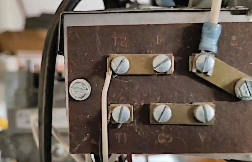
Step 2: Behind the Modine Heater
Turn to the back of the Modine heater to access the wiring.
Step 3: Wire Connections
The Modine heater terminals have the following functions:
- L1, L2, etc. – electric load terminals
- T1, T2, etc. – starter or motor terminals
- X1, X2, etc. – transformer secondary terminals
Attach the wires to the terminals on the unit as follows:
- Attach the black wire to the T1 terminal.
- Attach the white wire to the T2 terminal.
Step 4: Open the Thermostat Cover
We shall now turn our attention to wiring at the thermostat end. The one shown below was wired from before.
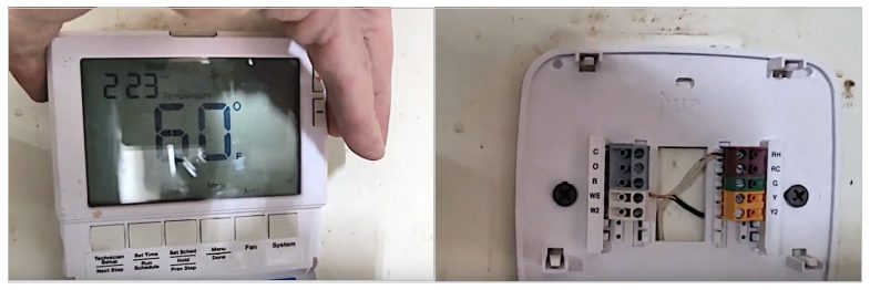
Open the thermostat cover from its baseplate to reveal the wiring points inside.
Step 5: Strip the Wires
Strip about half an inch of the insulation off the ends of the wires coming out of the wall using a wire stripper.
Step 6: Attach the Wires
Here’s a closer look at the terminals:
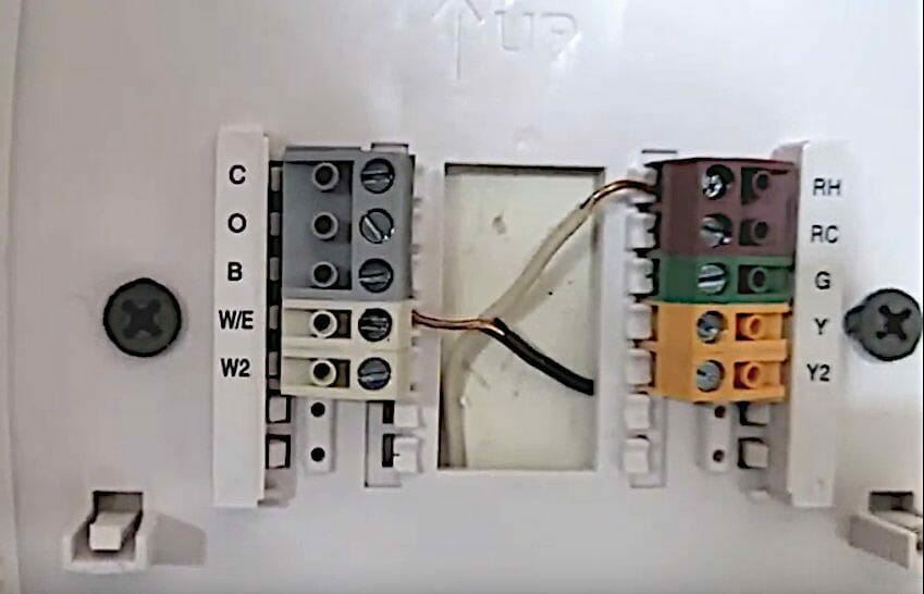
The thermostat terminals have the following functions:
- C – common, usually connected by blue/black wire
- E – emergency heat
- G – fan, usually connected by green wire
- O – heat pump
- R – power, usually connected by red wire
- W – heating system, usually connected by white wire
- Y – cooling, usually connected by yellow wire
You only need the R and W terminals in a simple setup to get the Modine heater working. Usually, you connect the wire from T1 to the R terminal and from T2 to the W terminal. However, consult the thermostat manual to determine the terminals to connect the wires. Otherwise, you can try the scheme given below.
Attach the wires to the following thermostat terminals in a typical 2-wire thermostat:
- Attach the black (or red) wire to the white block’s W/E (or W1) terminal.
- Attach the white wire to the RH terminal on the brown block.
A 3-wire thermostat used for water heaters has an additional green wire connecting to the G terminal to power the fan.
A 4-wire thermostat, which supports extra features such as cooling, has two extra yellow and blue wires. They connect to the Y terminals.
If any of the above doesn’t work, you must see the wiring diagram for your specific model because there are many models and variances.
Step 7: Secure the Wires
Ensure all the wire connections are secure. Loose connections can cause problems.
Step 8: Replace the Cover
Once the wiring inside the thermostat is done, you can re-attach the cover plate.
Wiring Variant Heater Types
Wiring a Gas-Fired Modine Heater
If you have a gas-fired Modine heater, you will have two black wires from the thermostat. One will be marked L (low) and the other H (high). In this case, attach them to the corresponding terminals on the Modine heater.
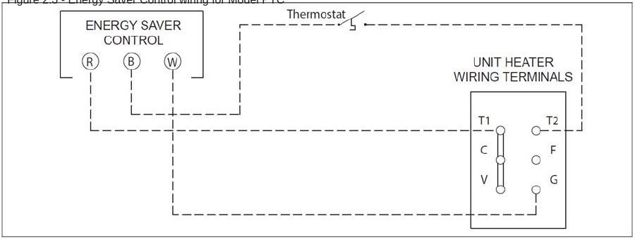
Modine HD/HDB, HDS/HDC, PTP, and PTS/BTS Models
- Connect Terminal T1 on the heater to Terminal R on the energy-saver control module.
- Connect Terminal T2 on the heater to Terminal B on the energy-saver control module via the thermostat.
- Connect Terminal G on the heater to Terminal W on the energy-saver control module.
Modine PDE Models
Modine PDE models are gas-fired unit heaters.
The wiring diagram for attaching a thermostat to this heater is shown below.
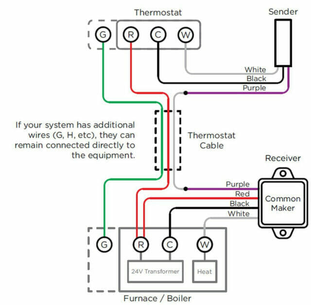
As you can see, the heater has no T terminals; rather, they correspond to the typical thermostat terminal labels. The system also uses a sender and receiver unit. The wires on these models are connected as follows:
- Connect the red wire to join both R terminals (on the thermostat and the heater) and an additional red wire from the heater’s R terminal to the receiver unit.
- Connect the black wire from the thermostat’s C terminal to the sender unit and the heater’s C terminal to the receiver unit.
- Likewise, connect the white wire from the thermostat’s W terminal to the sender unit and the heater’s W terminal to the receiver unit.
- Connect the green wire to join both G terminals on the thermostat and heater.
Other Models
For other Modine heater models not covered in this article. See your thermostat’s manual or wiring diagram here.
References
Website Resources:
- Modine heater manuals and diagrams. https://www.manualslib.com/brand/modine-manufacturing/heater.html
Video References:
Google Nest
Neglected Euros