4 min read
What is DCA on a Multimeter?
DCA on a multimeter stands for Direct Current Amperage. The DC (direct current) is a one-directional flow of the electrons (electric charges). Amperes is the unit that is used to measure the amount of current. The DC flows in conductors such as wires and semiconductors like insulators. Most of our electrical appliances use DC.
Multimeters can be used to extrapolate the load of current consumed in the circuit.
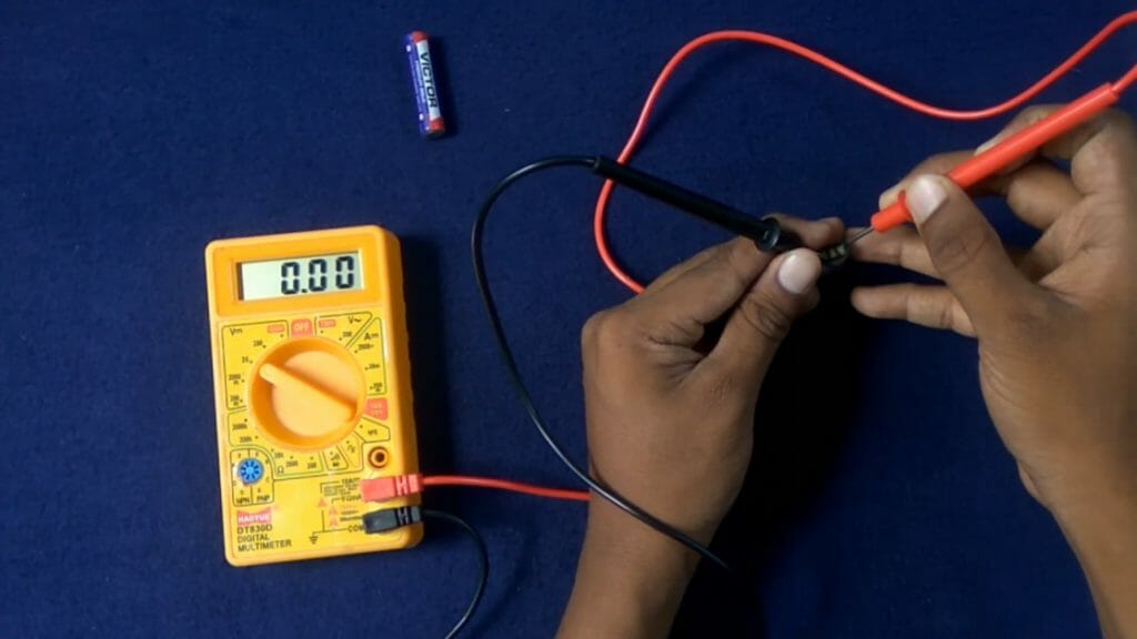
Multimeters can be used to measure different electrical properties of any material – the resistance (Ohms), DCA, and DCV. To measure the DCA of a circuit, select DC on your multimeter using the adjusting knob. Using the meter probes, complete the circuit and note the reading. The reading indicates the amount of current the circuit consumes.
Why Measure the DCA of Circuits?
It is important to measure the amount of current consumed by a circuit. The DCA current is required for power measurement. The amount of power dissipated or consumed is computed by multiplying voltage and current. Therefore, the process of measuring the DCA current needs to be very precise and accurate. The wrong measurement of DCA can cause big losses and damage. In this guide, I will teach you how to properly set your circuit and measure the DCA using a multimeter.
What you Need for this Experiment
To conduct this experiment, you need the following tools:
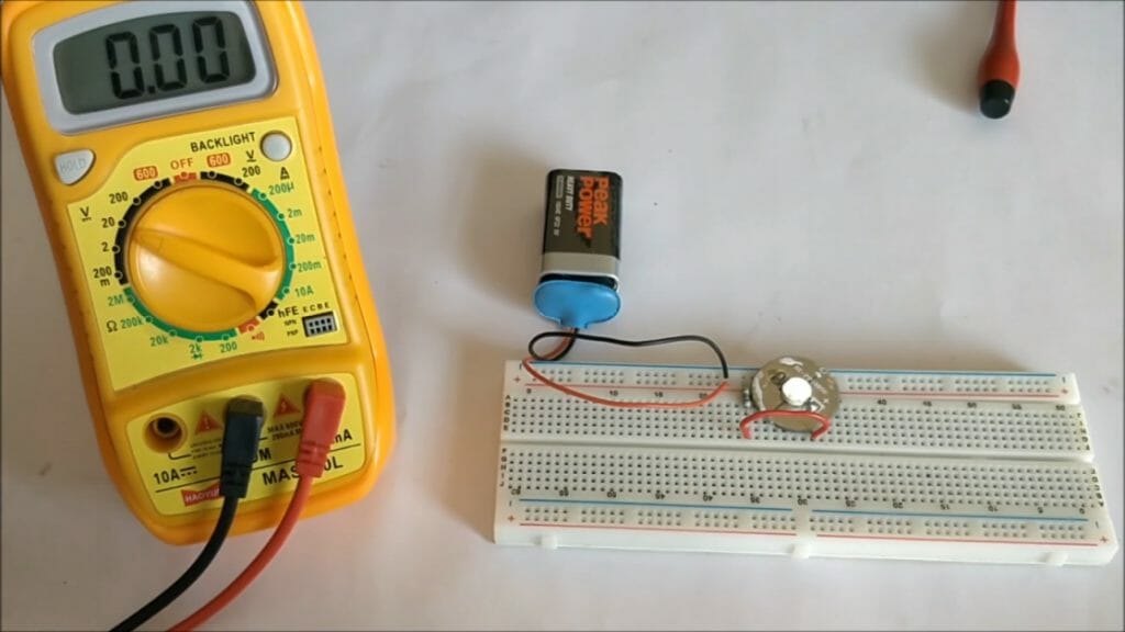
- A multimeter with probes
- Connecting wires
- A switch (in this case, the multimeter will act as the switch)
- A battery (source of voltage)
- A load (use a light or a bulb)
- Clips
- Adhesive tape
Setting Up the Circuit and Measuring the DC
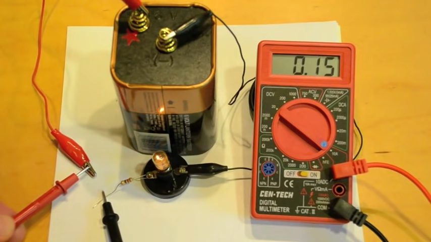
You will need to set up a circuit to perform this experiment. Follow the below-mentioned steps to set up your circuit, and measure the DC (in the circuit). (1)
- Connect your wires to the positive and negative terminals of the battery. You may use clips to fasten the wires or adhesive tape.
- Run the wire from the positive terminal of the battery to the red probe of the multimeter.
- Now connect the wire running from the negative terminal of the battery to one end of the bulb. And then complete the circuit by connecting the black probe from the COM section of the multimeter to the other end of the bulb.
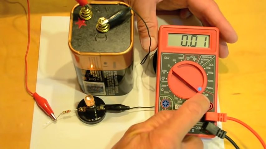
- Note the reading on the display unit. The DC value shows the amount of current consumed by the circuit. If the voltage value is known, you can multiply it with the DC value and get the total power in the circuit.
Important Points to Note in this Experiment
Use the following hints to avoid damaging your multimeter fuse:
- Plug the red probe in the correct port on the multimeter. The voltage source will help you predict the amount of DC. For higher voltage values, use the port marked 10A, and for lower voltage values use the port labeled as mA, 200 mA maximum. Plugging the red probe in the wrong port can damage your multimeter fuse.
- Do not place the probe leads directly to the power source terminals or the battery in our case. That only happens when you are measuring the voltage. Direct connection of probes to the battery can cause a short circuit, and will most likely blow your fuse. It happens if the current exceeds 10mA.
- The bulb must glow, otherwise, your battery is dead, or the connection is unsuitable. Be sure to follow the connecting steps accordingly.
Take a look at some of our related articles below.
- How to test battery with multimeter
- How to test a fluorescent light bulb with a multimeter
- How to measure DC voltage with a multimeter
Reference
(1) experiment – https://www.thoughtco.com/what-is-an-experiment-607970
Video References
Circuit Digest
MrChanPhysics
Slideo Studios