7 min read
How to Wire a GFCI Outlet with 6 Wires (7 Steps)
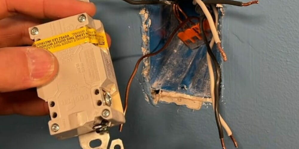
A GFCI outlet provides greater protection than a regular outlet. This makes them popular for safety and convenience, especially in moist areas. Don’t be confused by the number of wires. They are just three pairs of similar wires, plus the ground wire.
Like other power outlets with three wires, you connect the wires as follows (for US domestic AC): The three hot (black) wires connect to the bronze terminal, the three neutral (white) wires connect to the silver terminal, and the ground wires (green, green-yellow, or bare) connect to the ground terminal.
Firstly, let me explain the three-wire system a GFCI outlet relies on.
GFCI Outlets
GFCI outlets protect against electrical shock by detecting minor changes in current flow, which makes them ideal for kitchens, bathrooms, and outdoor areas.
However, they are larger than regular outlets and a bit more expensive.
GFCI Outlet Wires
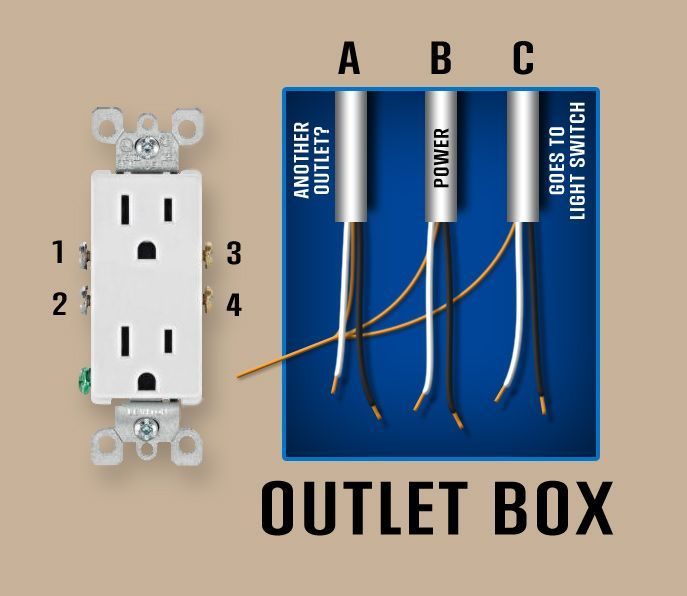
One set of wires provides the incoming power (marked B above). The other two (A and C) will be for two appliances, an appliance and an additional outlet on the same circuit.
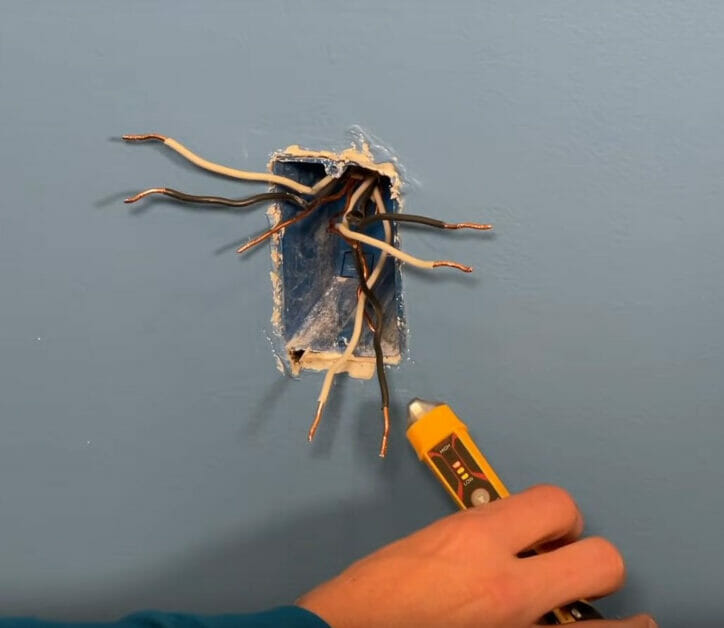
If you’re unsure which pair of wires are for power, you can use a voltage tester, as shown below. In this case, it’s the bottom pair, as the tester lit up fully when brought close to them.
The Line and Load Terminals
If you’re connecting wires from another outlet, i.e., not only other appliances, you will need to be aware of the line and load terminals.
They are marked in the illustration below. The power wires will connect to the line terminals, and the other pairs of wires will connect to the load terminals.
All ground wires will connect to the ground terminal.
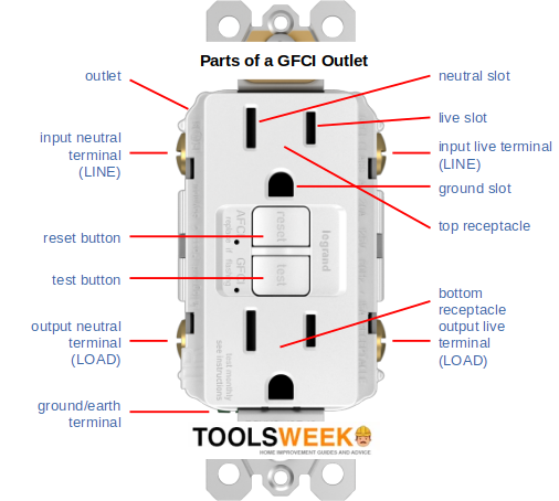
Although there are six wires, they are of three different types and connect to the GFCI outlet’s ‘hot,’ ‘neutral,’ and ‘ground’ connectors (see the picture below).
GFCI Outlet Terminals
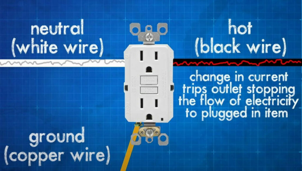
The three hot (black) wires are live conductors that power the main GFCI outlet or bring electrical current into the load.
The three neutral (white) wires provide a path for the current to return.
The single ground connection (usually green or bare) protects against ground faults caused by short circuits.
Each of the three must be connected to the right terminal: the hot wires to the bronze terminals, the neutral wires to the silver terminals, and the ground wire to the ground terminal.
This wiring scheme is according to the US wiring system for domestic AC. The colors and terminals may differ if you live elsewhere, including the outlet’s design.
Wiring a GFCI Outlet with Six Wires
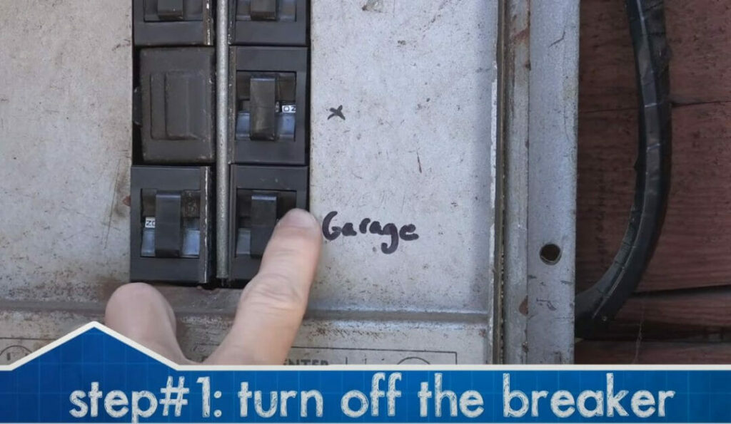
Step 1: Turn the Power Off
Firstly, turn the power off to the circuit to which the outlet will be connected.
Do this by switching off the corresponding circuit breaker at the main panel.
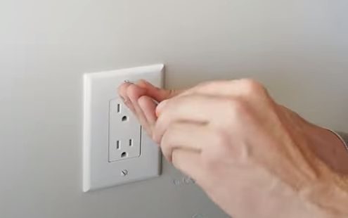
Step 2: Disconnect and Remove the Outlet (if applicable)
If removing an existing outlet, remove its cover plate by removing the screw. If this doesn’t apply, move on to Step 2.
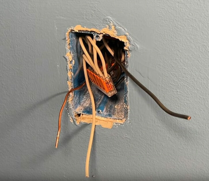
Then, completely disconnect the wiring behind the existing outlet. Remove the screws holding them behind the outlet. You might only need to loosen them and pull the wire ends out.
You can gently pull the entire outlet out when all the wires have been removed by holding two opposite sides.
Step 3: Strip the Wires (if Needed)
At this point, you might need to strip the ends of the wires.
If the wire ends are not adequately exposed, use a wire stripper to remove about half an inch of the insulation. There should be enough wire extending at least 4 inches from the box.
Step 4: Combine the Wires
When combining like wires, you can create pigtails, wire nuts, or use assortment clips, as shown below.
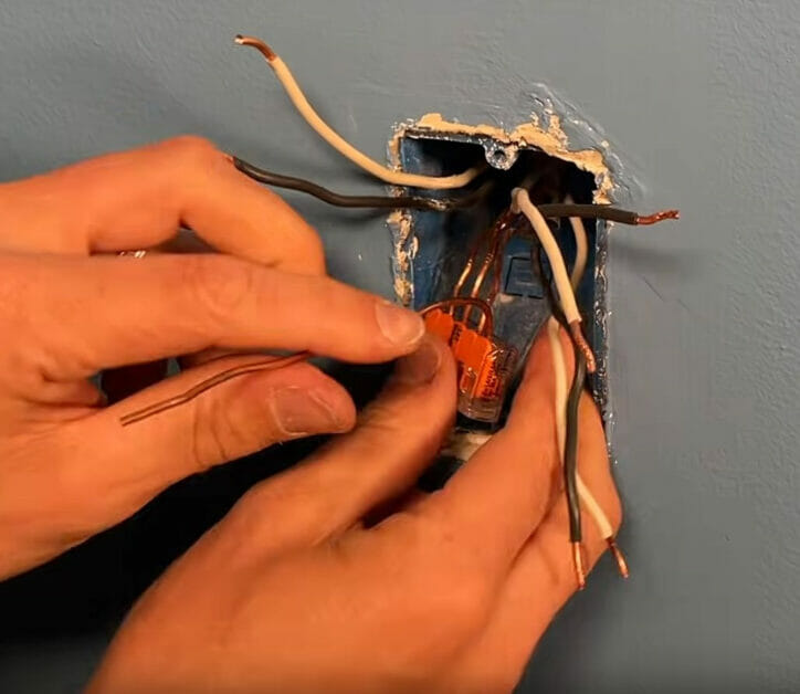
Repeat the same for the other wires.
When you are done combining like wires, tuck the connectors inside. You will end up with only three wires sticking out, which we will connect to the GFCI outlet.
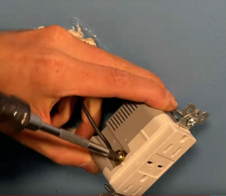
Step 5: Attach the Wires
Now, attach the wires to the new GFCI terminal.
Attach the wires according to the following scheme (for US domestic AC):
- Attach the black wire to the brass screw on the terminal marked ‘Hot’ or ‘Black.’
- Attach the white wire to the silver screw on the terminal marked ‘Neutral’ or ‘White.’
- Attach the ground wire to the green screw on the terminal marked ‘GRD’ or ‘Ground.’
Use nose pliers if you need to wrap a wire around its terminal. If the ground wire is bare copper, ensure it does not touch other terminals.
If connecting another outlet, note that the power supply wires (black and white) are connected to the ‘Line’ row. The ‘Load’ row allows the other outlets to connect with the GFCI outlet. If the GFCI terminal is new, the load terminals will probably be covered by tape, so you may need to remove it first.
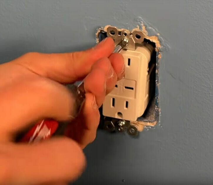
Step 6: Attach the Outlet
Once all the wiring is done, securely attach the outlet to its box in the wall and replace the cover plate.
Step 7: Power the Outlet On
Finally, you can turn the outlet on.
Your new GFCI outlet is now ready to use.
References
Website Resources:
- The six wires are explained and retrieved from https://diy.stackexchange.com/questions/83344/wall-outlet-with-three-sets-of-wires
Video References:
CircuitBread
Everyday Home Repairs
MrFixItDIY