10 min read
How to Test Solar Panels with a Multimeter (3-Step Guide)
Solar panels are usually tested under standard conditions using a light source that mimics the light from the sun on a clear day.
You can use the following method if you want to test your solar panel under standard conditions.
Testing solar panels is easy with a multimeter!
- To test the current, simply connect the multimeter to the panel’s output. Set it to read DC current. Now, measure the current of the panel by connecting your multimeter.
- To test voltage, set your multimeter to read AC voltage. Connect the multimeter to one of your panels’ output terminals and then measure the voltage.
- To test resistance, place one probe of your meter on a wire while placing another probe on an insulated part of the solar cell or module. The meter will give you a reading in ohms (Ω).
Step 1: Measure Open Circuit Voltage (Voc)
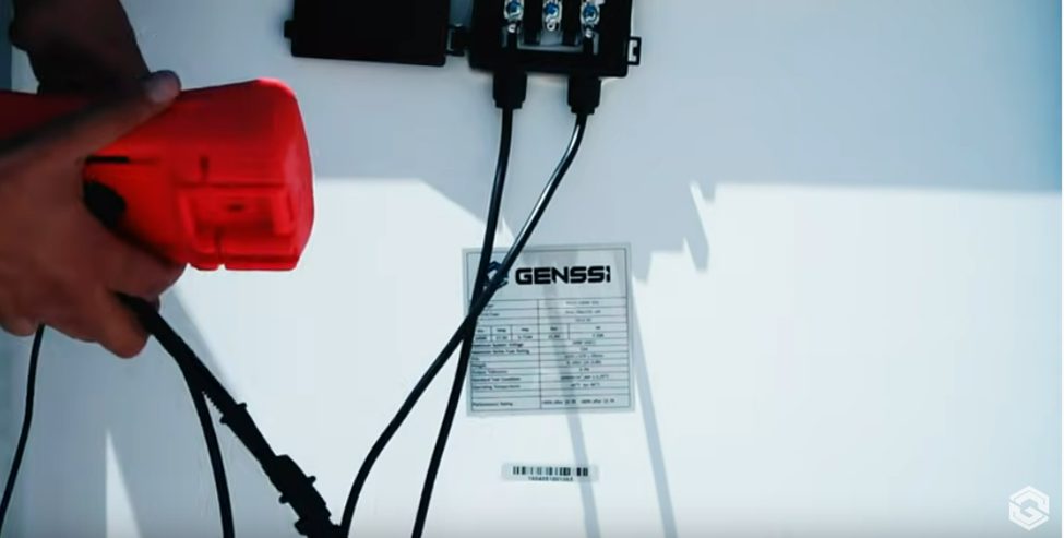
Different solar panels will have information on the sticker on the back showing how to test. (1)
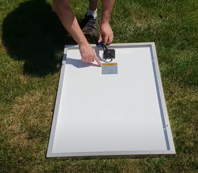
Using a voltage meter, locate the open-circuit voltage (Voc) on the specifications label on the back of your solar panel. Write it down for later use.
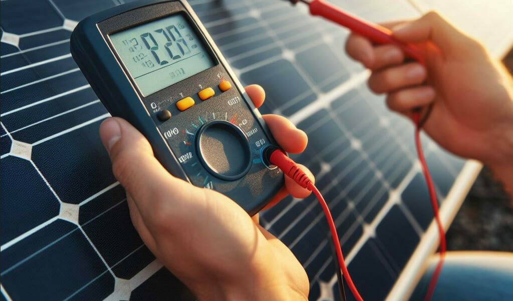
To measure the voltage of a DC circuit, you should prepare your multimeter by plugging the black probe into the COM terminal and the red probe into the voltage terminal.
A multimeter is usually set to measure DC voltage. To select this setting, one should rotate the dial with the letter V written on it until the solid line above a dotted line is in the position corresponding to the required voltage range.
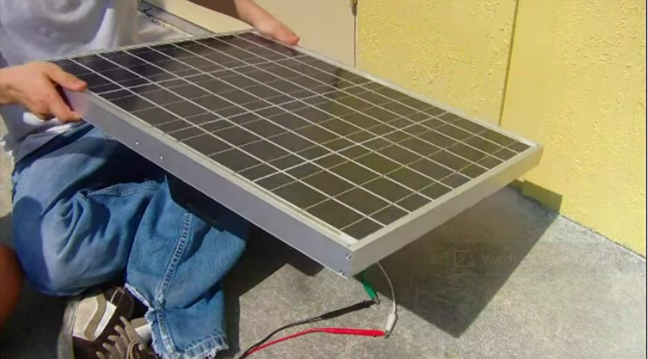
Place your solar panel in direct sunlight. Angle it towards the sun for optimal results.
Solar panels have positive and negative cables that must be matched to one another. The positive cable usually has a red MC4 connector, while the negative cable is typically black or white.
Place the red (positive) probe of the multimeter into the positive MC4 connector. Place the black (negative) probe of the multimeter into the negative MC4 connector.
Measure the voltage at the output terminals of the inverter with a multimeter and record it. (If your voltage reading is negative, reverse the probes and measure again.)
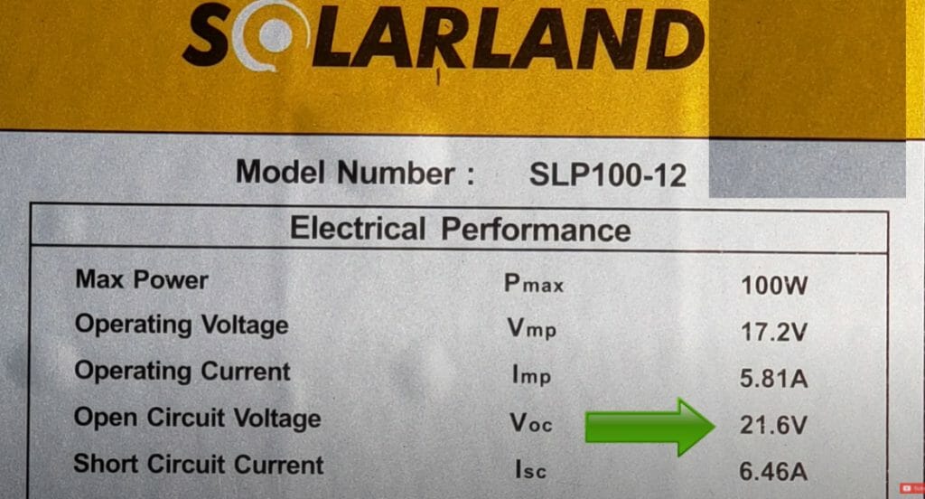
The measured Voc on my 12V solar panel was 19.85V. Since the panel’s claimed Voc is 19.83V, this is an accurate measurement.
The voltage you connect your voltmeter to should be close to the open-circuit voltage listed on the panel. However, it does not have to exactly match the label on the datasheet.
If the resistances in both circuits are the same, your panel is in good condition. You can proceed to the next step and measure the short circuit current.
When you measure the voltage of a solar panel, you should get about the same voltage as the VOC. Here are some things to try if your measurement is off:
- To ensure your solar panel can convert sunlight into electricity, the panel must be in direct sunlight, angled toward the sun, and not shaded.
- The solar panel should be positioned in a way that no part of the panel will be shaded.
- The solar panel should be clean.
If your measurement indicates an error or the measurement is still off, or if the reading is different every time you measure, your solar panel may be damaged.
Step 2: Measure Short Circuit Current (Isc)
The short circuit current (Isc) on a circuit panel is located on the specifications label on the back of the panel. Record this number for later use.
To prepare your multimeter to measure amps, move the red probe to the amperage terminal and set your multimeter to the amp setting (A). If your multimeter is not automatic-ranging, be sure to choose the right limit.
Warning: The fuse size on your multimeter should be greater than the short circuit current of the panel being tested. For example, if a panel’s short circuit current is 6.56A, then the multimeter should have a fuse size of 10A or larger.
Put your panel outside in direct sunlight.
Place the red (live) probe of your multimeter on the pin inside the positive MC4 connector. Place the black (ground) probe on the pin inside the negative MC4 connector.
Warning: After you complete the connection, a spark may jump between the two ends. This is normal.
Comparing the current reading on your multimeter with the short circuit current listed on the back of your electrical panel will help you determine if an outlet is wired correctly.
When measuring short circuit current, it should be close to the one listed on the label on the back of the panel.
For example, my panel had an Isc of 6.56A, while the manufacturer claimed an Isc of 6.08A. It was a little hazy that morning, but I am not surprised at this difference. On a clear summer day at noon, I would expect the Isc to be nearly identical. (2)
Any ratio of current to a voltage that matches the Isc listed on the back of the panel means that the panel is working correctly.
You can also measure open circuit voltage and short circuit current to test that your solar panel is in good working order. In addition to this, you can perform two other tests on your solar panel: You can test the resistance of the panel and the power factor.
If your measurement is not close to the claimed Isc, try the following suggestions and measure again.
- To ensure peak efficiency, make sure the solar panel is being exposed to direct sunlight.
- Make sure to test the solar panel close to noon.
- Aim the solar panel towards the sun during testing time.
- You should angle the solar panel so that no part of it is shaded.
- The solar panel should be clean.
In winter, solar panels have to work harder to produce the same amount of electricity as they would in summer. When your panels do not meet a certain output threshold, it might not be the panels’ fault. They might be working harder to compensate for the winter sun. In other words, they are doing what they are supposed to do.
Step 3: Measure Operating Current (aka PV Current)
You can also measure the voltage of a photovoltaic panel (PV Current) by connecting it to a charge controller.
It’s possible to use a multimeter to determine how much current your solar panel is outputting, but you’ll need an extra piece of equipment first.
- Solar charge controller
- Battery
Plug the solar charge controller into the battery.
Connect the input cables from the solar panel array to the charge controller.
Connect the cable that looks like a (-) symbol to the adapter cable with the same symbol. Do not connect the positive cable.
Like step two, you prepared the multimeter to measure amps. Now cover the solar panel or turn it face down on the ground so that it is not generating power.
To connect the solar panel to the charge controller, touch the red multimeter probe to the metal pin on the male MC4 connector (the one connected to the solar panel), and touch the black multimeter probe to the metal pin on the female MC4 connector (the one connected to the charge controller).
Uncover the solar panel or turn your solar panel face up (or upside down) and read the amperage output on your multimeter. I measured 4.46 A in output current on my multimeter.
You might try experimenting with the panel’s tilt angle and direction to see how these factors affect output.
If you compare the current reading to the solar panel’s maximum output power (the Imp on the back of the panel), you’ll see how close your solar panel is to its maximum capacity. In my case, my solar panel’s Imp is 6.26. I’m measuring a current of 4.46A.
While this may seem like a bad idea, it’s actually not that far off. Solar panels typically produce 70-80% of their rated power output in ideal conditions. In less than ideal conditions, such as on a cloudy day, you can expect to reach production levels closer to 100% of the panel’s rated power output.
Take a look at some of our related articles below.
- How to read ohms on a multimeter
- How to measure DC voltage with a multimeter
- How to use a multimeter to test voltage of live wires
References
(1) solar panels – https://www.britannica.com/technology/solar-panel
(2) summer – https://www.womansday.com/life/work-money/g1212/summer-activities/
Video References
GENSSI
fullmoonadventureclub
eMarine Systems
altE Store
lensunsolar